M28256-25NS6T Просмотр технического описания (PDF) - STMicroelectronics
Номер в каталоге
Компоненты Описание
производитель
M28256-25NS6T Datasheet PDF : 20 Pages
| |||
M28256
write cycle is complete, the toggling is stopped,
and the values read on DQ7-DQ0 are those of the
addressed memory byte. This indicates that the
device is again available for new Read and Write
operations.
Page Load Timer Status bit (DQ5). An internal
timer is used to measure the period between suc-
cessive Write operations, up to tWLQ5H (defined in
Table 9A and Table 9B). The DQ5 line is held low
to show when this timer is running (hence showing
that the device has received one write operation,
and is waiting for the next). The DQ5 line is held
high when the counter has overflowed (hence
showing that the device is now starting the internal
write to the memory array).
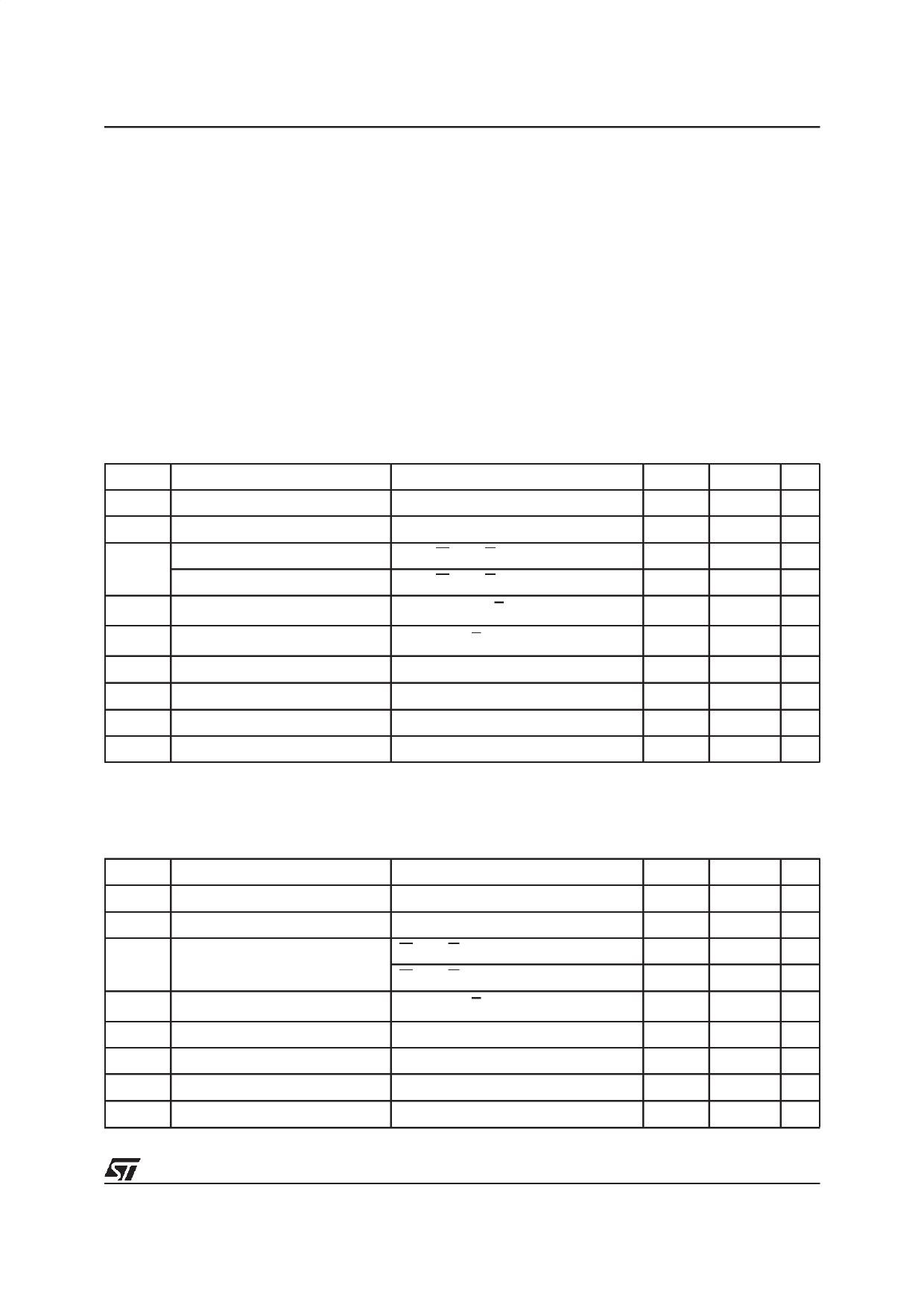
Table 5A. Read Mode DC Characteristics for M28256 (5V range)
(TA = 0 to 70 °C or -40 to 85 °C; VCC = 4.5 to 5.5 V)
Symbol
Parameter
Test Condi tion
ILI Input Leakage Current
0 V ≤ VIN ≤ VCC
ILO Output Leakage Current
0 V ≤ VOUT ≤ VCC
ICC 1
Supply Current (TTL inputs)
Supply Current (CMOS inputs)
E = VIL, G = VIL , f = 5 MHz
E = VIL, G = VIL , f = 5 MHz
ICC1 1 Supply Current (Stand-by) TTL
E = VIH
ICC2 1 Supply Current (Stand-by) CMOS
E > VCC – 0.3V
VIL Input Low Voltage
VIH Input High Voltage
VOL Output Low Voltage
IOL = 2.1 mA
VOH Output High Voltage
Note: 1. All inputs and outputs open circuit.
IOH = –400 µA
Min.
–0.3
2
2.4
Max.
10
10
30
25
Unit
µA
µA
mA
mA
1
mA
100
µA
0.8
V
VCC + 0.5 V
0.4
V
V
Table 5B. Read Mode DC Characteristics for M28256-W (3V range)
(TA = 0 to 70 °C or -40 to 85 °C; VCC = 2.7 to 3.6 V)
Symbol
Parameter
Test Condi tion
ILI Input Leakage Current
0 V ≤ VIN ≤ VCC
ILO Output Leakage Current
0 V ≤ VOUT ≤ VCC
ICC 1 Supply Current (CMOS inputs)
E = VIL, G = VIL , f = 5 MHz, VCC = 3.3V
E = VIL, G = VIL , f = 5 MHz, VCC = 3.6V
ICC2 1 Supply Current (Stand-by) CMOS
E > VCC – 0.3V
VIL Input Low Voltage
VIH Input High Voltage
VOL Output Low Voltage
IOL = 1.6 mA
VOH Output High Voltage
Note: 1. All inputs and outputs open circuit.
IOH = –400 µA
Min.
Max. Unit
10
µA
10
µA
15
mA
15
mA
20
µA
–0.3
0.6
V
2
VCC + 0.5 V
0.2 VCC V
0.8 VCC
V
7/20
Share Link: 