AIC1848CG Просмотр технического описания (PDF) - Analog Intergrations
Номер в каталоге
Компоненты Описание
производитель
AIC1848CG Datasheet PDF : 10 Pages
| |||
AIC1848
VCFLY, that is, 2VIN.
VIN
Q1
Q2 VOUT
CIN
CFLY
COUT
Q3
Q4
Fig. 11 The circuit of charge pump
Short Circuit/Thermal Protection
AIC1848 obtains built-in short circuit current
limiting and over temperature protection. During
the short circuit condition, the output current is
automatically constrained at approximately
300mA. Continued current limit will cause internal
IC junction temperature increased. When the
temperature of device exceeds 150°C, the
thermal protection will shut the switching down
and the temperature will reduce afterwards. Once
the temperature drops below 135°C, the charge
pump switching circuit will re-start. If the fault
doesn’t eliminate, the above protecting operation
will repeat again and again. It allows AIC1848 to
continuously work at short circuit condition without
damaging the device.
Shutdown
In shutdown mode, the output is disconnected
from input. The input current gets extremely low
since most of the circuitry is turned off. Due to
high impedance, shutdown pin can’t be floated.
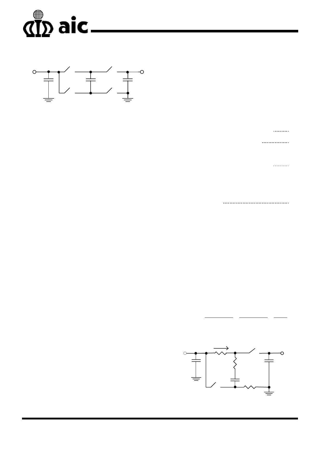
Efficiency
Refer to Fig. 12 and Fig. 13, they shows the circuit
of charge pump at different operation states.
RDS-ON is the resistance of the switching element
at conduction.
ESR is the equivalent series resistance of the
flying capacitor CFLY.
ION-AVE and IOFF-AVE are the average current
during on state and off state, respectively.
D is the duty cycle, which means the proportion
the on state takes.
Let’s take advantage of conversation of charge for
capacitor CFLY. Assume that the capacitor CFLY
has reached its steady state. The amount of
charge flowing into CFLY during on state is equal
to that flowing out of CFLY at off state.
ION−AVE × DT = IOFF−AVE × (1 − D)T
(1)
ION-AVE × D = IOFF-AVE × (1− D)
(2)
IIN = ION-AVE × D + IOFF-AVE × (1− D)
= 2 × ION-AVE × D
(3)
= 2 × IOFF-AVE × (1- D)
IOUT = IOFF-AVE × (1− D)
IIN = 2 × IOUT
(4)
For AIC1848, the controller takes the PWM (Pulse
Width Modulation) control strategy. When the duty
cycle is limited to 0.5, there will be:
ION-AVE × 0.5 × T = IOFF-AVE × (1− 0.5) × T
ION-AVE = IOFF-AVE
According to the equation (4), we know that as
long as the flying capacitor CFLY is at steady state,
input current is double of output current. The
efficiency of charge pump is given below:
η = VOUT × IOUT = VOUT × IOUT = VOUT
VIN × IIN
VIN × 2IOUT 2VIN
VIN
CIN
ION
RDS-ON-Q1 ESR Q2
CFLY
VOUT
COUT
Q3
RDS-ON-Q4
Fig. 12 The on state of charge pump circuit
7
Share Link: 