ADR280 Просмотр технического описания (PDF) - Analog Devices
Номер в каталоге
Компоненты Описание
производитель
ADR280 Datasheet PDF : 12 Pages
| |||
ADR280
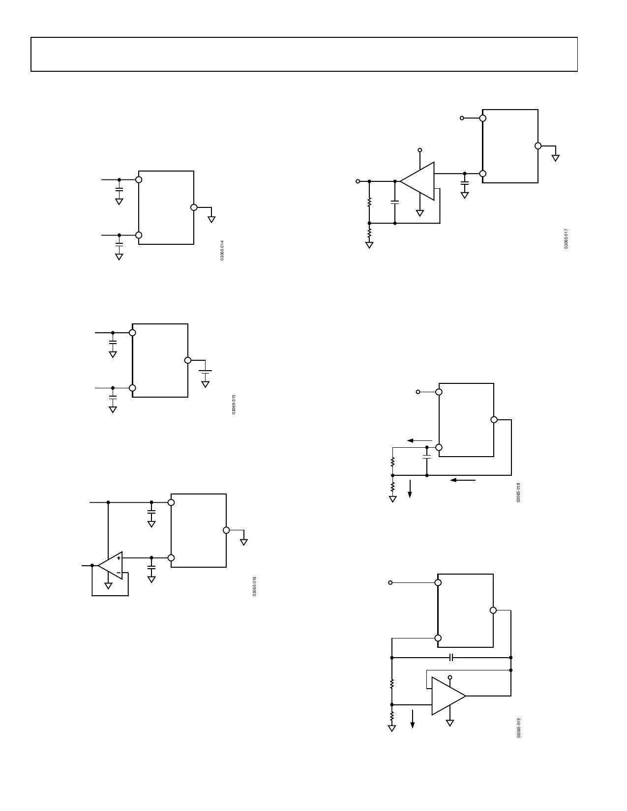
APPLICATIONS INFORMATION
The ADR280 should be decoupled with a 0.1 μF ceramic
capacitor at the output for optimum stability. It is also good
practice to include 0.1 μF ceramic capacitors at the IC supply
pin. These capacitors should be mounted close to their
respective pins (see Figure 12).
0.1µF
V+
ADR280
V–
U1
5V
V+
ADR280
5V
V–
VO
1.8V
R2
60kΩ ± 0.1%
C2
2.2pF
U2 V+ +
AD8541
V– –
1.2V
C1
0.1µF
VOUT
0.1µF
VOUT
Figure 12. Basic Configuration
The low supply voltage input pin V− can be elevated above
ground; a 1.2 V differential voltage can therefore be established
above V− (see Figure 13).
5V
0.1µF
V+
ADR280
V–
1.2V + V–
0.1µF
VOUT
2.5V
Figure 13. Floating References
The ADR280 provides the core 1.2 V band gap voltage and is
able to drive a maximum load of only 100 μA. Users can simply
buffer the output for high current or sink/source current applica-
tions, such as ADC or LCD driver references (see Figure 14).
U1
0.1µF
V+
ADR280
V–
U2
VOUT
VOUT
0.1µF
U2 = AD8541, SC70
AD8601, SOT-23-5
Figure 14. Buffered Output
Users can also tailor any specific need for voltage and dynamics
with an external op amp and discrete components (see Figure 14
and Figure 15). Depending on the specific op amp and PCB
layout, it may be necessary to add a compensation capacitor, C2,
to prevent gain peaking and oscillation. The exact value of C2
needed requires some trial and error but usually falls in the
range of a few picofarads.
R1
120kΩ ± 0.1%
Figure 15. 1.8 V Reference
LOW COST, LOW POWER CURRENT SOURCE
Because of its low power characteristics, the ADR280 can be
converted to a current source with just a setting resistor. In
addition to the ADR280 current capability, the supply voltage
and the load limit the maximum current. The circuit in Figure 16
produces 100 μA with 2 V compliance at a 5 V supply. The load
current is the sum of ISET and IGND. IGND increases slightly with
load; a RSET of 13.6 kΩ yields 100 μA of load current.
U1
5V
V+
ADR280
V–
ISET
RSET +
C1
0.1µF
1.2V – 13.6kΩ
VOUT
RL
1kΩ
IL
100µA
IGND
IL = ISET + IGND
Figure 16. Low Cost Current Source
Precision Low Power Current Source
By adding a buffer to redirect the IGND in Figure 17, a current
can be precisely set by RSET with the equation IL = 1.2 V/RSET.
U1
5V
V+
ADR280
V–
VOUT
C2
0.1µF
RSET
12kΩ
RL
1kΩ
5V
– V+ U2
AD8541
+ V–
IL
100µA
IL = 1.2V/RSET
Figure 17. Precision Low Power Current Source
Rev. C | Page 8 of 12
Share Link: 