ADM8699 Просмотр технического описания (PDF) - Analog Devices
Номер в каталоге
Компоненты Описание
производитель
ADM8699 Datasheet PDF : 4 Pages
| |||
ADM8698/ADM8699
CIRCUIT INFORMATION
Power Fail RESET
A precision voltage detector monitors VCC and generates a
RESET output to hold the microprocessor’s Reset line low when
VCC falls below the reset threshold 4.65 V (see Figure 4). The
reset voltage threshold is set to accommodate a 5% variation on
VCC. The voltage detector has 40 mV hysteresis to ensure that
glitches on VCC do not activate the RESET output.
On power-up, an internal monostable holds RESET low for
140 ms after VCC rises above the reset threshold. This allows the
power supply to stabilize on power-up and also prevents repeated
toggling of RESET even if the 5 V power drops out and recovers
with each power line cycle. In order to prevent mistriggering
due to transient voltage spikes, it is recommended that a 0.1 µF
capacitor be connected at the VCC pin.
The RESET output is guaranteed to remain low with VCC, as
low as 1 V. This holds the microprocessor in a stable shutdown
condition as the power supply comes up.
On the 16-lead SOIC package, an active high RESET output is
also provided. This is the complement of RESET and is in-
tended for microprocessors requiring an active high signal.
Watchdog Timer (ADM8699 Only)
The watchdog timer input (WDI) monitors an I/O line from the
µP system. The µP must toggle this input once every 1.6 sec-
onds to verify correct software execution. Failure to toggle the
line indicates that the µP system is not correctly executing its
program and may be tied up in an endless loop. If this happens,
a reset pulse is generated to initialize the processor.
The WDI input is a three level input and will recognize a low-
to-high or high-to-low transition on its input. The watchdog
timer is reset by each WDI transition and then begins its timeout
period. If the WDI pin remains either high or low, reset pulses
will be issued every 1.6 seconds typically. If the watchdog timer
is not needed, the WDI input should be left floating.
The Watchdog Output (WDO) (SOIC package Only) provides
watchdog status information. It is driven low if WDI is not
toggled within the watchdog timeout period. It goes high at the
next WDI transition. It is also set high when VCC falls below the
reset threshold.
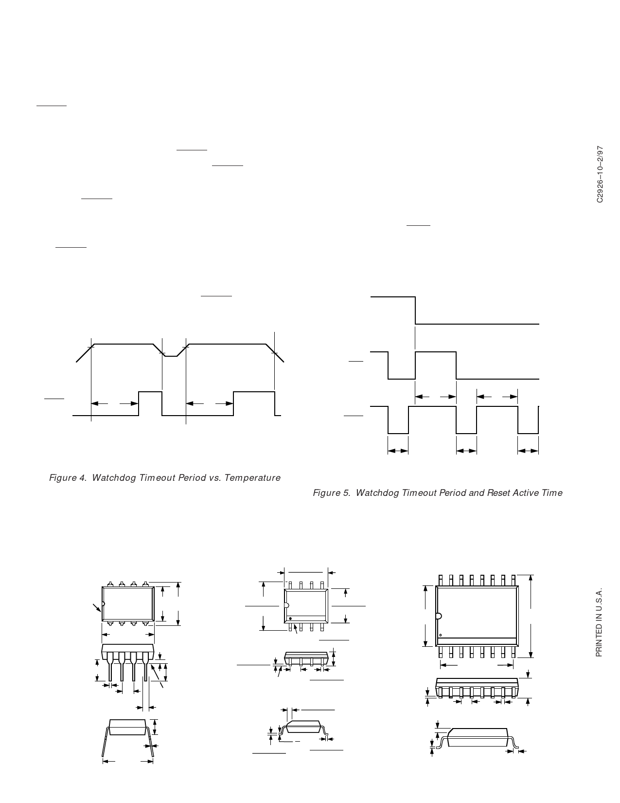
WDI
VCC
V2
V1
V2
V1
WDO
RESET
t1
t1
V1 = RESET VOLTAGE THRESHOLD
V2 = RESET VOLTAGE THRESHOLD +
THRESHOLD HYSTERESIS
t1 = RESET TIME
Figure 4. Watchdog Timeout Period vs. Temperature
t2
t2
RESET
t1
t1
t1
tt12
=
=
RESET TIME
WATCHDOG
TIME
OUT
PERIOD
Figure 5. Watchdog Timeout Period and Reset Active Time
8-Pin Plastic DIP (N-8)
8
PIN 1
1
5
0.25 0.31
(6.35) (7.87)
4
0.430 (10.92)
MAX
0.035
(0.89)
0.18 (4.57)
0.018 (0.46)
0.1 (2.54)
BSC
0.011
(0.28)
0.3 (7.62)
0.125
(3.18)
MIN
SEATING
PLANE
0.033 (0.84)
0.18
(4.57)
MAX
OUTLINE DIMENSIONS
Dimensions shown in inches and (mm).
8-Pin SOIC (R-8)
0.1968 (5.00)
0.1890 (4.80)
8
0.2440 (6.20)
0.2284 (5.80) 1
5
0.1574 (4.00)
4 0.1497 (3.80)
PIN 1 0.102 (2.59)
0.094 (2.39)
0.0098 (0.25)
0.0040 (0.10)
SEATING
PLANE
0.0500
(1.27)
BSC
0.0192 (0.49)
0.0138 (0.35)
0.0196
0.0099
(0.50)
(0.25)
x
45°
8°
0.0098 (0.25) 0° 0.0500 (1.27)
0.0075 (0.19)
0.0160 (0.41)
–4–
16-Lead SOIC (R-16)
16
0.299
(7.60)
1
9
0.419
(10.65)
8
0.012
(0.3)
0.030
(0.75)
0.013
(0.32)
0.413 (10.50)
0.104
(2.65)
0.05 (1.27) 0.019 (0.49)
REF
0.042
(1.07)
REV. 0
Share Link: 