ADM1033ARQ-REEL7 Просмотр технического описания (PDF) - Analog Devices
Номер в каталоге
Компоненты Описание
производитель
ADM1033ARQ-REEL7 Datasheet PDF : 40 Pages
| |||
ADM1033
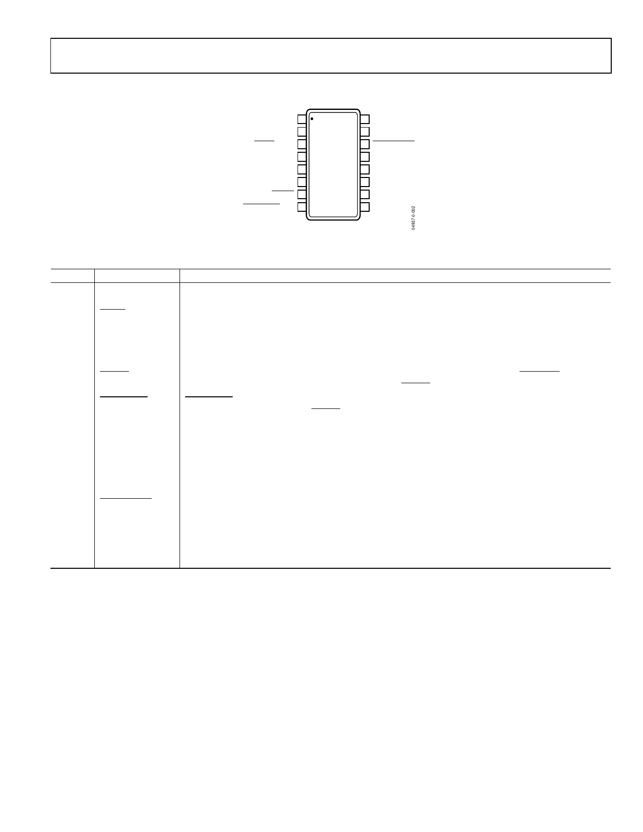
PIN CONFIGURATION AND FUNCTION DESCRIPTIONS
DRIVE 1
TACH 2
ALERT Comp 3
NC 4
GND 5
VCC 6
THERM 7
FAN_FAULT/REF 8
16 SCL
15 SDA
ADM1033
TOP VIEW
(Not to Scale)
14 SMBusALERT
13 LOCATION
12 NC
11 NC
10 D+
9 D–
NC = NO CONNECT
Figure 3. Pin Configuration
Table 3. Pin Function Descriptions
Pin No. Mnemonic
Description
1
DRIVE
DRIVE Pin Drives the Fan. Open-drain output. Requires a pull-up resistor.
2
TACH
Fan Speed Measurement Input. Connects to the fan’s TACH output to measure the fan speed.
3
ALERT Comp
Open-Drain Active Low Output. Asserts low whenever a measurement goes outside its programmed limits,
if not masked. Automatically goes high again when the measured parameter falls back within its limits.
4
NC
No Connect.
5
GND
Ground for Analog and Digital Circuitry.
6
VCC
Power. Can be powered by 3.3 V standby power, if monitoring in low power states is required.
7
THERM
Can be configured as an overtemperature interrupt output, or as an input to monitor PROCHOT output of
an INTEL CPU. A timer measures assertion times on the THERM pin (either input or output).
8
FAN_FAULT/REF FAN_FAULT: Open-Drain Output. Asserts low whenever the fan stalls.
REF: Analog Input Reference for THERM input.
9
D−
Cathode Connection for the Thermal Diode or Diode-Connected Transistor.
10
D+
Anode Connection for the Thermal Diode or Diode-Connected Transistor.
11
NC
No Connect.
12
NC
No Connect.
13
LOCATION
8-Level Analog Input. Used to determine the correct SMBus version and the SMBus address (in fixed-and-
discoverable mode), and to set the LLL bits in the UDID (in ARP-capable mode).
14
SMBusALERT
Open-Drain Output. Alerts the system in the case of out-of-limit events such as overtemperature. Can be
reset only with software.
15
SDA
Serial Bus Bidirectional Data. Connects to the SMBus master’s data line. Requires a pull-up resistor, if one is
not provided elsewhere in the system.
16
SCL
Serial SMBus Clock Input. Connects to the SMBus master’s clock line. Requires a pull-up resistor, if one is
not provided elsewhere in the system.
Rev. 0 | Page 7 of 40
Share Link: 