AD534LD Просмотр технического описания (PDF) - Analog Devices
Номер в каталоге
Компоненты Описание
производитель
AD534LD Datasheet PDF : 12 Pages
| |||
AD534
OPERATION AS A DIVIDER
The AD535, a pin-for-pin functional equivalent to the AD534,
has guaranteed performance in the divider and square-rooter
configurations and is recommended for such applications.
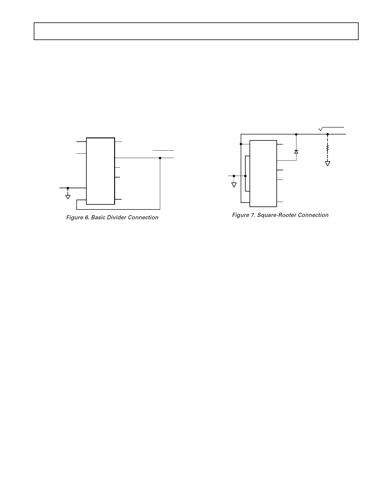
Figure 6 shows the connection required for division. Unlike
earlier products, the AD534 provides differential operation on
both numerator and denominator, allowing the ratio of two
floating variables to be generated. Further flexibility results from
access to a high impedance summing input to Y1. As with all
dividers based on the use of a multiplier in a feedback loop, the
bandwidth is proportional to the denominator magnitude, as
shown in Figure 23.
X INPUT +
(DENOMINATOR)
+10V FS
+12V PK –
OPTIONAL
SUMMING
INPUT
؎10V PK
X1
+VS
X2
OUT
SF
Z1
AD534
Z2
Y1
Y2
–VS
+15V
OUTPUT, ؎12V PK
=
10V (Z2 – Z1)
(X1 – X2)
+
Y1
Z INPUT
(NUMERATOR)
؎10V FS, ؎12V PK
–15V
Figure 6. Basic Divider Connection
Without additional trimming, the accuracy of the AD534K
and L is sufficient to maintain a 1% error over a 10 V to 1 V
denominator range. This range may be extended to 100:1 by
simply reducing the X offset with an externally generated trim
voltage (range required is ± 3.5 mV max) applied to the unused
X input (see Figure 1). To trim, apply a ramp of +100 mV to
+V at 100 Hz to both X1 and Z1 (if X2 is used for offset adjust-
ment, otherwise reverse the signal polarity) and adjust the trim
voltage to minimize the variation in the output.*
Since the output will be near +10 V, it should be ac-coupled for
this adjustment. The increase in noise level and reduction in
bandwidth preclude operation much beyond a ratio of 100 to 1.
As with the multiplier connection, overall gain can be intro-
duced by inserting a simple attenuator between the output and
Y2 terminal. This option, and the differential-ratio capability of
the AD534 are utilized in the percentage-computer application
shown in Figure 12. This configuration generates an output
proportional to the percentage deviation of one variable (A) with
respect to a reference variable (B), with a scale of one volt per
percent.
OPERATION AS A SQUARE ROOTER
The operation of the AD534 in the square root mode is shown
in Figure 7. The diode prevents a latching condition which
could occur if the input momentarily changes polarity. As
shown, the output is always positive; it may be changed to a
negative output by reversing the diode direction and interchang-
ing the X inputs. Since the signal input is differential, all combi-
nations of input and output polarities can be realized, but
operation is restricted to the one quadrant associated with each
combination of inputs.
OUTPUT, ؎12V PK
= 10V (Z2 – Z1) +X2
OPTIONAL
SUMMING
INPUT,
X, ؎10V PK
X1
+VS
X2
OUT
SF
Z1
AD534
Z2
Y1
Y2
–VS
+15V
REVERSE
THIS AND X
INPUTS FOR
NEGATIVE
OUTPUTS
– Z INPUT
10V FS
+ 12V PK
RL
(MUST BE
PROVIDED)
–15V
Figure 7. Square-Rooter Connection
In contrast to earlier devices, which were intolerant of capacitive
loads in the square root modes, the AD534 is stable with all
loads up to at least 1000 pF. For critical applications, a small
adjustment to the Z input offset (see Figure 1) will improve
accuracy for inputs below 1 V.
*See the AD535 data sheet for more details.
REV. B
–7–
Share Link: 