AD5342 Просмотр технического описания (PDF) - Analog Devices
Номер в каталоге
Компоненты Описание
производитель
AD5342 Datasheet PDF : 20 Pages
| |||
TERMINOLOGY
RELATIVE ACCURACY
For the DAC, Relative Accuracy or Integral Nonlinearity (INL)
is a measure of the maximum deviation, in LSBs, from a straight
line passing through the actual endpoints of the DAC transfer
function. Typical INL versus Code plot can be seen in Figures
5, 6, and 7.
DIFFERENTIAL NONLINEARITY
Differential Nonlinearity (DNL) is the difference between the
measured change and the ideal 1 LSB change between any two
adjacent codes. A specified differential nonlinearity of ± 1 LSB
maximum ensures monotonicity. This DAC is guaranteed mono-
tonic by design. Typical DNL versus Code plot can be seen in
Figures 8, 9, and 10.
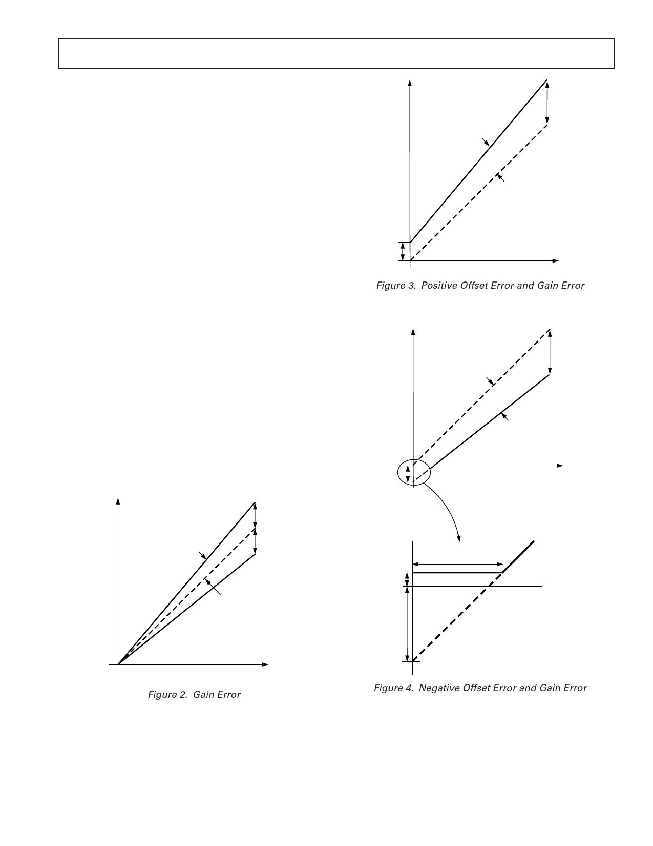
OFFSET ERROR
This is a measure of the offset error of the DAC and the output
amplifier. It is expressed as a percentage of the full-scale range.
If the offset voltage is positive, the output voltage will still be
positive at zero input code. This is shown in Figure 3. Because
the DACs operate from a single supply, a negative offset cannot
appear at the output of the buffer amplifier. Instead, there will
be a code close to zero at which the amplifier output saturates
(amplifier footroom). Below this code there will be a deadband
over which the output voltage will not change. This is illustrated
in Figure 4.
GAIN ERROR
This is a measure of the span error of the DAC (including any
error in the gain of the buffer amplifier). It is the deviation in
slope of the actual DAC transfer characteristic from the ideal
expressed as a percentage of the full-scale range. This is illus-
trated in Figure 2.
ACTUAL
POSITIVE
GAIN ERROR
NEGATIVE
GAIN ERROR
OUTPUT
VOLTAGE
IDEAL
AD5332/AD5333/AD5342/AD5343
OUTPUT
VOLTAGE
ACTUAL
GAIN ERROR
AND
OFFSET
ERROR
IDEAL
POSITIVE
OFFSET
DAC CODE
Figure 3. Positive Offset Error and Gain Error
OUTPUT
VOLTAGE
NEGATIVE
OFFSET
IDEAL
GAIN ERROR
AND
OFFSET
ERROR
ACTUAL
DAC CODE
AMPLIFIER
FOOTROOM
(~ 1mV)
DEADBAND CODES
NEGATIVE
OFFSET
DAC CODE
Figure 2. Gain Error
Figure 4. Negative Offset Error and Gain Error
REV. 0
–9–
Share Link: 