A1242 Просмотр технического описания (PDF) - Allegro MicroSystems
Номер в каталоге
Компоненты Описание
производитель
A1242 Datasheet PDF : 11 Pages
| |||
A1242
Two-Wire Chopper-Stabilized Hall Effect Latch
Functional Description
OPERATION
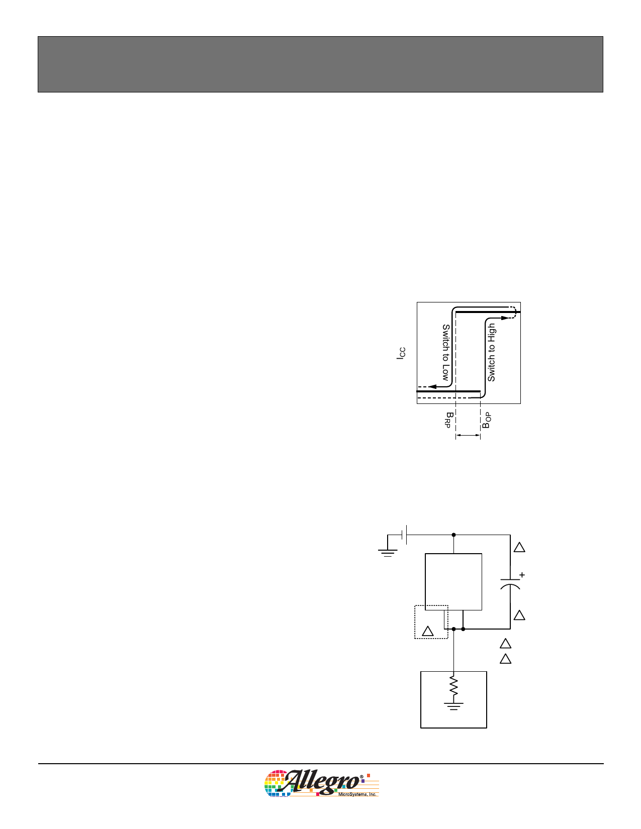
The output, ICC, of the A1242 switches to the high current state
when a magnetic field perpendicular to the Hall sensor exceeds
the operate point threshold, BOP. Note that the device latches,
that is, a south pole of sufficient strength towards the branded
surface of the device switches the device output to ICC(H). The
device retains its output state if the south pole is removed. When
the magnetic field is reduced to below the release point thresh-
old, BRP, the device output goes to the low current state. The dif-
ference between the magnetic operate and release points is called
the hysteresis of the device, BHYS. This built-in hysteresis allows
clean switching of the output even in the presence of external
mechanical vibration and electrical noise.
.
TYPICAL APPLICATION CIRCUIT
The A1242 should be protected by an external bypass capaci-
tor, CBYP, connected between the supply, VCC, and the ground,
GND, of the device. CBYP reduces both external noise and the
noise generated by the chopper-stabilization function. As shown
in figure 2, a 0.01 μF capacitor is typical.
Installation of CBYP must ensure that the traces that connect it to
the A1242 pins are no greater than 5 mm in length.
All high-frequency interferences conducted along the supply
lines are passed directly to the load through CBYP, and it serves
only to protect the A1242 internal circuitry. As a result, the load
ECU (electronic control unit) must have sufficient protection,
other than CBYP, installed in parallel with the A1242.
A series resistor on the supply side, RS (not shown), in combina-
tion with CBYP, creates a filter for EMI pulses.
When determining the minimum VCC requirement of the A1242
device, the voltage drops across RS and the ECU sense resistor,
RSENSE, must be taken into consideration. The typical value for
RSENSE is approximately 100 Ω.
Extensive applications information on magnets and Hall-effect
sensors is available in:
• Hall-Effect IC Applications Guide, AN27701,
• Hall-Effect Devices: Gluing, Potting, Encapsulating, Lead Welding
and Lead Forming, AN27703.1
• Soldering Methods for Allegro Products – SMD and Through-Hole,
AN26009
All are provided in Allegro Electronic Data Book, AMS-702
and the Allegro Web site: www.allegromicro.com.
I+
ICC(H)
0
B–
0
ICC(L)
B+
BHYS
Figure 1. Switching Behavior of the A1242. On the horizontal axis, the
B+ direction indicates increasing south polarity magnetic field strength,
and the B– direction indicates decreasing south polarity field strength
(including the case of increasing north polarity).
V+
VCC
B
A1242
GND
A
GND
CBYP
0.01 uF
B
A Package UA Only
B Maximum separation 5 mm
RSENSE
A1242-DS
ECU
Figure 2. Typical Application Circuit
Allegro MicroSystems, Inc.
7
115 Northeast Cutoff, Box 15036
Worcester, Massachusetts 01615-0036 (508) 853-5000
www.allegromicro.com
Share Link: 