A1242 Просмотр технического описания (PDF) - Allegro MicroSystems
Номер в каталоге
Компоненты Описание
производитель
A1242 Datasheet PDF : 11 Pages
| |||
A1242
Two-Wire Chopper-Stabilized Hall Effect Latch
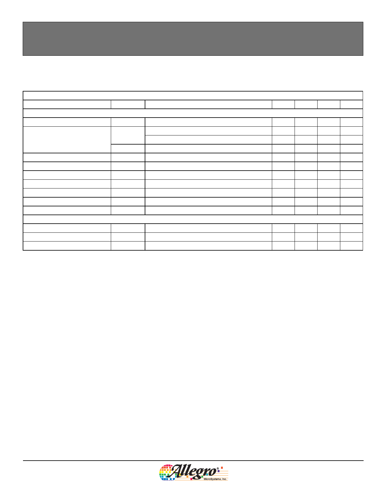
ELECTRICAL CHARACTERISTICS over full operating voltage and temperature ranges, unless otherwise specified
Characteristic
Symbol
Test Conditions
Min. Typ.1 Max. Units
Electrical Characteristics
Supply Voltage2 3
Supply Current
VCC
ICC(L)
Operating, TJ < 165°C
-I1, B < BRP
-I2, B < BRP
3.5
–
24
V
5
–
6.9
mA
2
–
5
mA
Output Slew Rate4
Chopping Frequency
ICC(H)
dI/dt
fC
-I1 and -I2, B > BOP
RS = 100 Ω, CS = 20 pF, no bypass capacitor
12
–
17
mA
–
36
–
mA/μs
–
200
–
kHz
Power-On Time
Power-On State5
Supply Zener Clamp Voltage
Supply Zener Current6
Reverse Battery Current
Magnetic Characteristics7
tPO
POS
VZ(supply)
IZ(supply)
IRCC
VCC > VCC(MIN)
tPO < tPO(max), dVCC / dt > 25 mV / μs
ICC = 20 mA; TA = 25°C
VS = 28 V
VRCC = –18 V
–
–
25
μs
–
ICC(H)
–
–
28
–
–
V
–
–
20
mA
–
–
2.5
mA
Operate Point
Release Point
Hysteresis
BOP
BRP
BHYS
South pole adjacent to branded face of device
North pole adjacent to branded face of device
BOP – BRP
5
32
80
G
–80
–32
–5
G
40
64
110
G
1 Typical values are at TA = 25°C and VCC = 12 V. Performance may vary for individual units, within the specified maximum and minimum
limits.
2 Maximum voltage must be adjusted for power dissipation and junction temperature; see Power Derating section.
3 VCC represents the generated voltage between the VCC pin and the GND pin.
4 The value of dI is the difference between 90% of ICC(H) and 10% of ICC(L), and the value of dt is time period between those two points.
The value of dI/dt depends on the value of the bypass capacitor, if one is used, with greater capacitances resulting in lower rates of
change.
5 For t > tPO(max), and BRP < B < BOP, POS is undefined.
6 Maximum current limit is equal to the maximum ICCL(max) + 3 mA.
7 Magnetic flux density, B, is indicated as a negative value for north-polarity magnetic fields, and as a positive value for south-polarity
magnetic fields. This so-called algebraic convention supports arithmetic comparison of north and south polarity values, where the relative
strength of the field is indicated by the absolute value of B, and the sign indicates the polarity of the field (for example, a –100 G field and
a 100 G field have equivalent strength, but opposite polarity).
DEVICE QUALIFICATION PROGRAM
Contact Allegro for information.
EMC (Electromagnetic Compatibility) PERFORMANCE
Contact Allegro for information.
A1242-DS
Allegro MicroSystems, Inc.
3
115 Northeast Cutoff, Box 15036
Worcester, Massachusetts 01615-0036 (508) 853-5000
www.allegromicro.com
Share Link: 