DSP1N5S17 Просмотр технического описания (PDF) - Power-One Inc.
Номер в каталоге
Компоненты Описание
производитель
DSP1N5S17 Datasheet PDF : 3 Pages
| |||
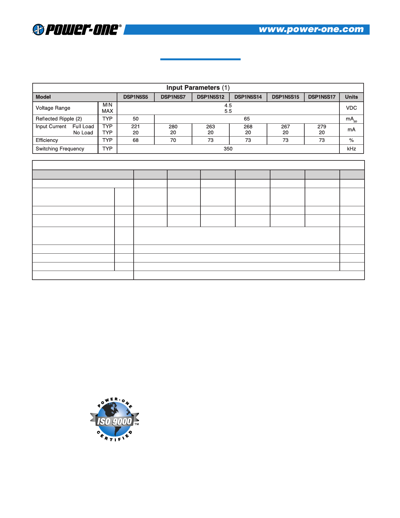
DSP1 SERIES – SINGLE OUPUT
Model
Output Voltage
Output Voltage Accuracy (3)
Output Voltage, No Load
Rated Load Range
Load Regulation (4)
75% - 20% Load
75% - 100% Load
Line Regulation (5)
MIN
TYP
MAX
TYP
MIN
MAX
TYP
TYP
TYP
Noise, Peak - Peak (2)
TYP
Temperature Coefficient
TYP
Short Circuit Protection to Common (6)
Output Parameters (1)
DSP1N5S5 DSP1N5S7 DSP1N5S12 DSP1N5S14
5
7
12
14
4.75
6.65
11.40
13.30
5.00
7.00
12.00
14.00
5.25
7.35
12.60
14.70
7
10
16
19
0
0
0
0
150
140
80
70
DSP1N5S15
15
14.25
15.00
15.75
21
0
65
+8
-5
1.6
70
400
Momentary
DSP1N5S17
17
16.15
17.00
17.85
24
0
60
Units
VDC
VDC
VDC
mA
%
%
mVPP
ppm/°C
NOTES
(1) All parameters measured at Tc=25°C, nominal input voltage and full rated load unless otherwise noted.
(2) Measurement bandwidth is 20 MHz. Input Reflected Ripple and output noise are measured with an exter-
nal 10µF/25V tantalum capacitor connected across the input and output pins.
(3) Output Voltage Accuracy measured at 75% of maximum Rated Load.
(4) Load Regulations measured relative to 75% of maximum Rated Load Current.
(5) Line Regulation is for a 1.0% change in input Voltage.
(6) Use input fuse for protection. See Applying the input.
DSP1 SERIES APPLICATION NOTES:
External Capacitance Requirements
Output filtering is required for operation. A minimum of
10F is specified for optimal performance. Output capaci-
tance may be increased for additional filtering, not to
exceed 400F. To meet the reflected ripple requirements of
the converter, an input impedance of less than 0.5 Ohms
from DC to 350KHz is required. If a capacitive input source
is farther than 2” from the converter, it is recommended to
use a 10F, 25V solid tantalum capacitor.
Regulation
This converter uses a semi-regulated design. The output will
vary as the load is changed, with output decreasing with
increasing load. See Output Voltage vs. Output Load curves.
Additionally, output voltage will change in proportion to a
change in input voltage. The typical output voltage will
change 1.2% for each 1% change in input voltage.
Negative Outputs
A negative output voltage may be obtained by connecting
the +OUT to circuit ground and connecting -OUT as the
negative output.
2
Share Link: 