78Q2133_F Просмотр технического описания (PDF) - Unspecified
Номер в каталоге
Компоненты Описание
производитель
78Q2133_F Datasheet PDF : 42 Pages
| |||
78Q2123/78Q2133 MicroPHY™
10/100BASE-TX Transceiver
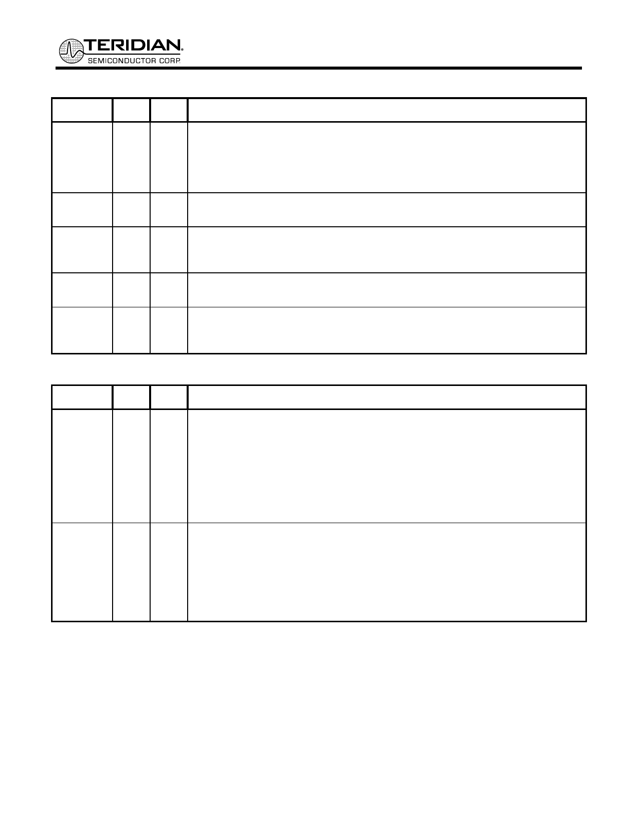
MII (MEDIA INDEPENDENT INTERFACE) (CONTINUED)
SIGNAL PIN TYPE DESCRIPTION
RX_DV 11 COZ RECEIVE DATA VALID: RX_DV is asserted high to indicate that valid data is
present on the RXD[3:0] pins. In 100BASE-TX mode, it transitions high with the first
nibble of the preamble and is pulled low when the last data nibble has been
received. In 10BASE-T mode it transitions high when the start-of-frame delimiter
(SFD) is detected. This pin is tri-stated in isolate mode.
RXD[3:0] [5:8] COZ RECEIVE DATA: Received data is provided to the MAC via RXD[3:0]. These pins
are tri-stated in isolate mode.
RX_ER 13 COZ RECEIVE ERROR: RX_ER is asserted high when an error is detected during frame
reception. In PCS bypass mode, this pin becomes the MSB of the receive 5-bit code
group. This pin is tri-stated in isolate mode.
MDC
2
CIS MANAGEMENT DATA CLOCK: MDC is the clock used for transferring data via the
MDIO pin.
MDIO
1
CIO MANAGEMENT DATA INPUT/OUTPUT: MDIO is a bi-directional port used to
access management registers within the 78Q2123/78Q2133. This pin requires an
external pull-up resistor as specified in IEEE-802.3.
CONTROL AND STATUS
SIGNAL PIN TYPE DESCRIPTION
RST
23 CIS ACTIVE LOW RESET: When pulled low the pin resets the chip. The reset pulse
must be long enough to guarantee stabilization of the supply voltage and startup of
the oscillator. Refer to the Electrical Specifications for the reset pulse requirements.
There are 2 other ways to reset the chip:
i. Through the internal power-on-reset (activated when the chip is being powered
up)
ii. Through the MII register bit (MR 0.15)
INTR
32 COZ INTERRUPT PIN: This pin is used to signal an interrupt to the media access
controller. The pin is held in the high impedance state when an interrupt is not
indicated. The pin will be forced high or low to signal an interrupt depending upon
the value of the INPOL bit (MR16.14). The events which trigger an interrupt can be
programmed via the Interrupt Control Register located at address MR17.
Page: 8 of 42
© 2009 Teridian Semiconductor Corporation
Rev 1.5
Share Link: 