74HC40103 Просмотр технического описания (PDF) - Integrated Circuit Systems
Номер в каталоге
Компоненты Описание
производитель
74HC40103 Datasheet PDF : 17 Pages
| |||
Philips Semiconductors
8-bit synchronous binary down counter
AC WAVEFORMS
Product specification
74HC/HCT40103
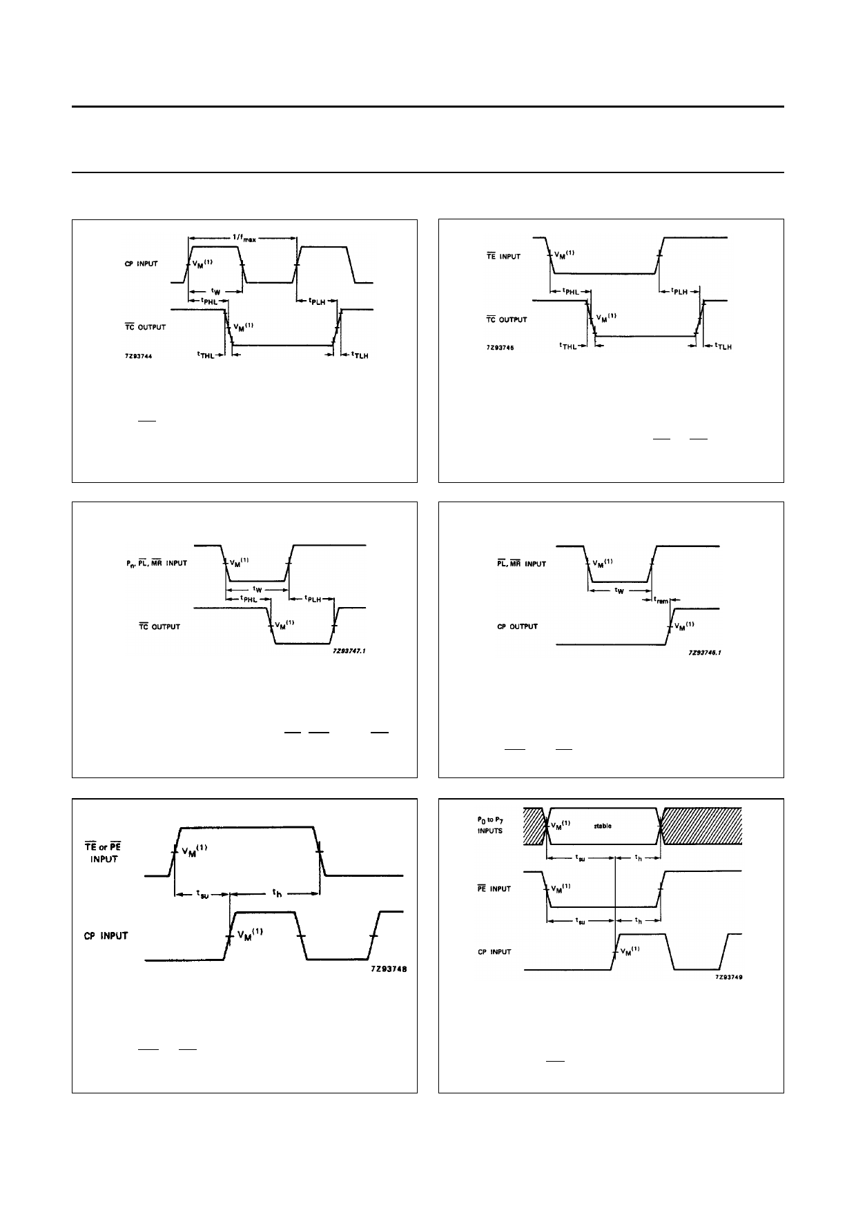
(1) HC : VM = 50%; VI = GND to VCC.
HCT: VM = 1.3 V; VI = GND to 3 V.
Fig.7
Waveforms showing the clock input (CP) to
TC propagation delays, the clock pulse width,
the output transition times and the maximum
clock pulse frequency.
(1) HC : VM = 50%; VI = GND to VCC.
HCT: VM = 1.3 V; VI = GND to 3 V.
Fig.8 Waveforms showing the TE to TC
propagation delays.
(1) HC : VM = 50%; VI = GND to VCC.
HCT: VM = 1.3 V; VI = GND to 3 V.
Fig.9 Waveforms showing PL, MR, Pn to TC
propagation delays.
(1) HC : VM = 50%; VI = GND to VCC.
HCT: VM = 1.3 V; VI = GND to 3 V.
Fig.10 Waveforms showing removal time for
MR and PL.
(1) HC : VM = 50%; VI = GND to VCC.
HCT: VM = 1.3 V; VI = GND to 3 V.
Fig.11 Waveforms showing hold and set-up times for
MR or PE to CP.
The shaded areas indicate when the input is permitted to change
for predictable output performance.
(1) HC : VM = 50%; VI = GND to VCC.
HCT: VM = 1.3 V; VI = GND to 3 V.
Fig.12 Waveforms showing hold and set-up times
for Pn, PE to CP.
1998 Jul 08
10
Share Link: 