2SC1881 Просмотр технического описания (PDF) - Hitachi -> Renesas Electronics
Номер в каталоге
Компоненты Описание
производитель
2SC1881 Datasheet PDF : 6 Pages
| |||
2SC1881(K)
Electrical Characteristics (Ta = 25°C)
Item
Symbol Min Typ
Collector to emitter breakdown V(BR)CEO 60
—
voltage
Emitter to base breakdown
V(BR)EBO
7
—
voltage
Collector cutoff current
DC current transfer ratio
I CBO
—
—
I CEO
—
—
hFE
1000 —
500 —
Collector to emitter saturation VCE(sat)
—
—
voltage
Turn on time
Turn off time
Note: 1. Pulse test.
t on
—
1
t off
—
5
Max Unit
—
V
—
V
0.2 mA
0.4 mA
—
—
1.2 V
—
µs
—
µs
Test conditions
IC = 50 mA, RBE = ∞
IE = 50 mA, IC = 0
VCB = 60 V, IE = 0
VCE = 30 V, RBE = ∞
VCE = 1.5 V
IC = 1.5 A*1
IC = 2.5 A*1
IC = 2.5 A, IB = 20 mA*1
VCC = 11 V, IC = 2 A,
IB1 = –IB2 = 8 mA
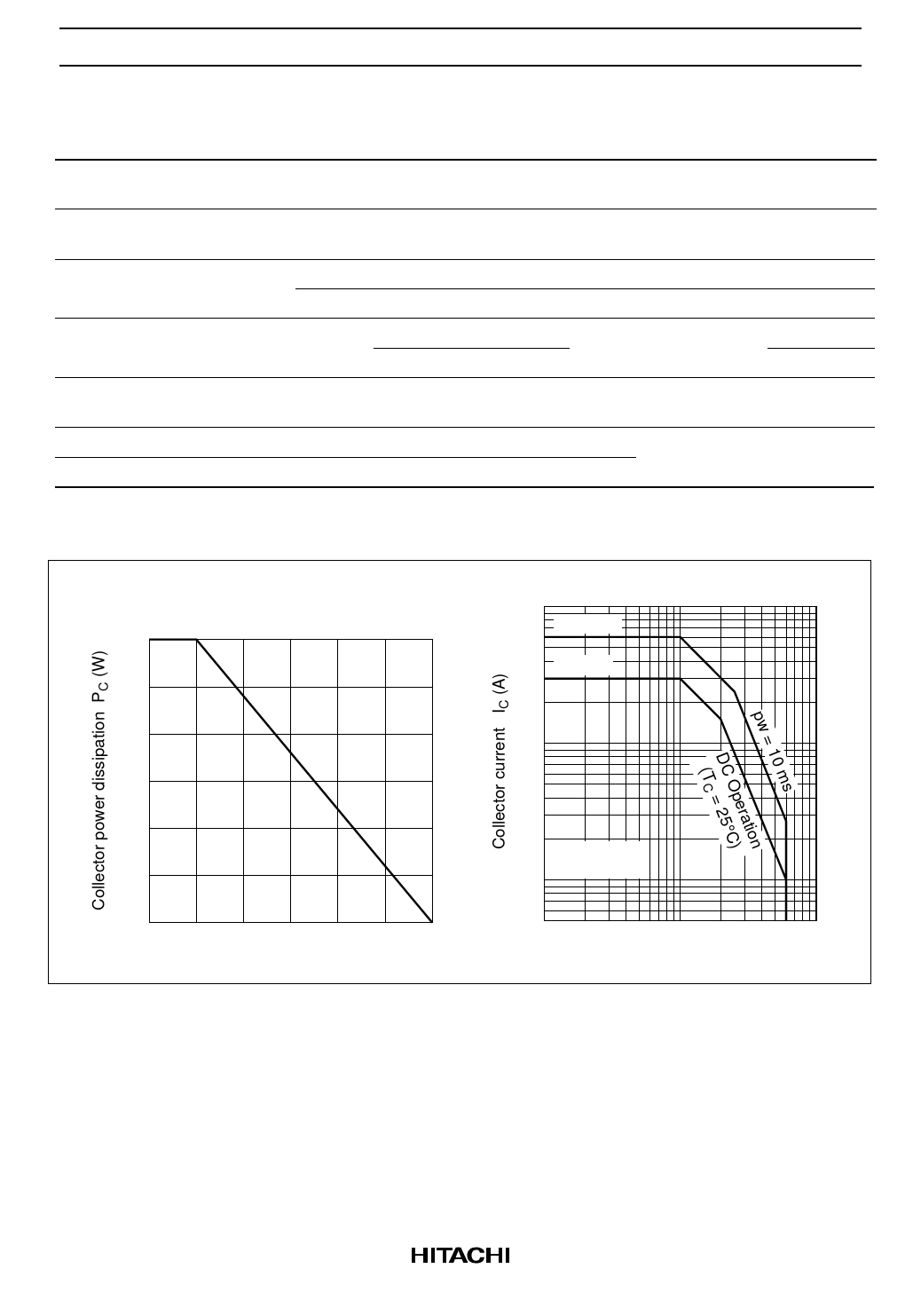
Maximum Collector Dissipation Curve
30
20
10
0
50
100
150
Case temperature TC (°C)
Area of Safe Operation
10
iC (peak)
5
IC max
2
1.0
0.5
0.2 Ta = 25°C
0.1 1 shot pulse
0.05
12
5 10 20 50 100
Collector to emitter voltage VCE (V)
2
Share Link: 