LA4627 Просмотр технического описания (PDF) - SANYO -> Panasonic
Номер в каталоге
Компоненты Описание
производитель
LA4627 Datasheet PDF : 6 Pages
| |||
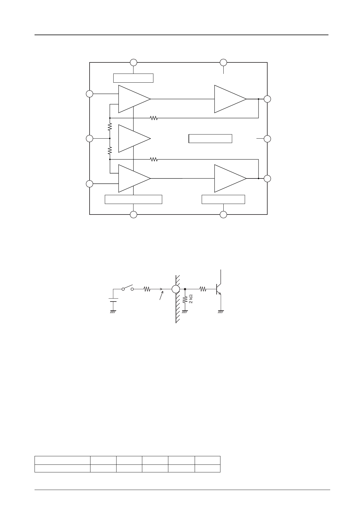
Block Diagram
ch1
Input 7
RNf1
PRE GND 4
RNf2
LA4627
STBY
1
Standby SW
ch1 input
amplifier
Rf1
REF
amplifier
Rf2
VCC
12
Output
amplifier
TSD protector
ch1
11 Output
Fin POWER GND
ch2
Input 6
ch2 input
amplifier
Pop noise prevention block
9
P.P
Pin Functions
1. Standby switch function (pin 1)
Output
amplifier
Ripple filter
8
Filter
ch2
2 Output
ILA00059
Applied standby
voltage Vx
Rx
STBY
1
+
The inflowing current at an
applied voltage of 1.5 V, i.e.
the point when the amplifier
turns on, is approximately
750 µA.
STBY pin applied voltage: 5 V
2 kΩ
ILA00058
To hold the pin 1 inflow current to about 750 µA insert a resistor (Rx) of 4.7 kΩ
STBY pin applied voltage: 12 V
To hold the pin 1 inflow current to about 750 µA insert a resistor (Rx) of 14 kΩ (12 kΩ).
STBY pin applied voltage: Other value (Vx)
To hold the pin 1 inflow current to about 750 µA insert a resistor (Rx) of (Vx - 1.5 V)/750 µA.
• If a microcontroller output signal is applied directly, insert a resistor in series
and adjust the current to a level optimal for the drive capability of the
microcontroller.
2. Input pins (pins 6 and 7)
The input pin voltage is about 2VBE (1.4 V).
The input pin impedance is about 30 kΩ.
• Although the recommended value for the input capacitor is 0.22 µF, the starting time can be modified by changing the
value of this capacitor. (The time from the point a voltage is applied to the standby pin to the point sound is emitted.)
Input capacitor 1.0 µF 2.2 µF 3.3 µF 4.7 µF 10 µF
Starting time (ts) 0.2 s 0.3 s 0.5 s 0.65 s 1.5 s
No.6501-3/6
Share Link: 