VN16218 Просмотр технического описания (PDF) - Vaishali Semiconductor
Номер в каталоге
Компоненты Описание
производитель
VN16218 Datasheet PDF : 11 Pages
| |||
VN16218
Advance Information
Name
RX[0:19]
RX+, RX-
TX+, TX-
VDDP
VSSP
TEST2
Pin #
65, 63, 59
57, 55, 52
50, 48, 45
43, 64 ,62
58, 56, 54
51,49,47
44, 42
68, 67
Type
O-TTL
I-diff
74, 75
O diff
76,78
77
80
P
P
I-TTL
Description
Receive Data Bus, Bits 0 through 19. 20 bit received data
character. Parallel data on this bus can be sampled on the rising
edge of RBC. R0 is the first bit received on RX+/RX-
Receiver serial inputs. The device recognizes receiver inputs when
EWR is LOW
Transmitter serial ouputs. When EWR is LOW, the serialized
transmit data is available on these pins. When EWR is HIGH, TX+
is HIGH and TX- is LOW
High-speed output driver power supply. Connect to 1.8V
High speed output driver ground. 0V
Test pin for Vaishali internal use only. User should tie this pin to
GND for normal operation
Legend: I = Input
O = Output
P = Power supply connection
Functional Block Description
PLL Clock Multiplier
The VN16218 employs a user-supplied 125 MHz clock both as a reference clock and as a Transmit Byte
Clock (TBC). The PLL Clock Multiplier multiplies the TBC by 20 to generate a baud rate clock of 2.5 GHz.
The TBC also clocks in the incoming parallel data.
Serializer (Parallel-to-Serial Converter)
Input data arrives at the T[0:19] bus as two parallel 10 bit characters and is latched into the input latch on
the rising edge of TBC. The data is serialized and transmitted on the TX differential outputs at a baud rate
of twenty times the frequency of TBC. Bit T0 is transmitted first. Incoming data is already encoded for
transmission using either the 8B/10B block code, as specified in the Fibre Channel specification, or an
equivalent edge-rich, DC-balanced code. If EWR is HIGH, the transmitter will be disabled, with TX+ HIGH
and TX- LOW. If EWR is LOW, the transmitter outputs serialized data. According to the fibre channel
specification, a transmission character is an encoded byte of 10 bits. The 20 bit interface of the VN16218
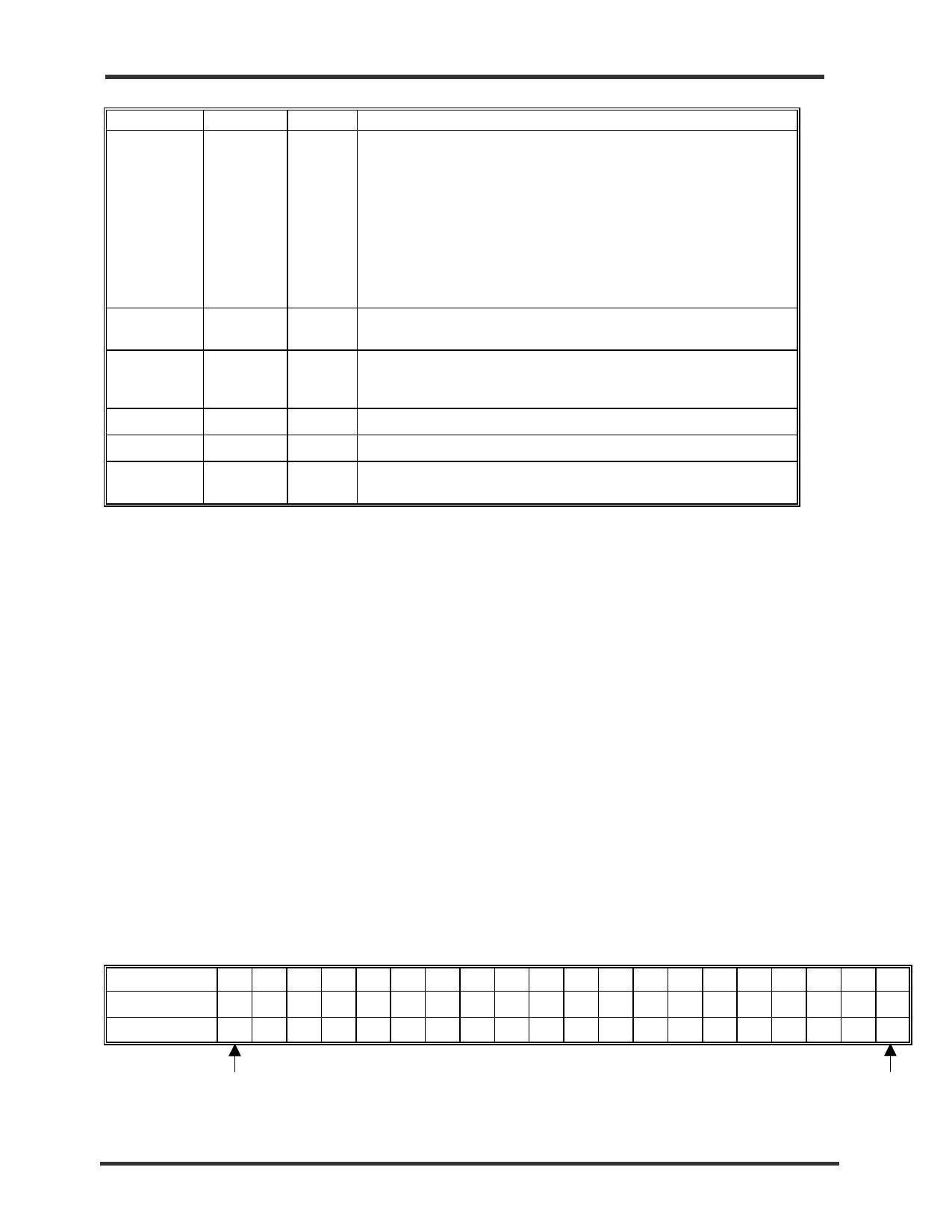
corresponds to two transmission characters, as shown in Table 2 below.
Table 2. Transmission Sequence and Mapping to Fibre Channel Character
Parallel Data Bits 19 18 17 16 15 14 13 12 11 10 09 08 07 06 05 04 03 02 01 00
8B/10Bit Position
j
hgf
i
edc baj
hgf
i
edc ba
Valid Comma Pos.
1111100
Last Data Bit Transmitted
First Data Bit Transmitted
2001-11-09
Page 4
MDSN-0003-00
www.vaishali.com
Vaishali Semiconductor 747 Camden Avenue, Suite C Campbell CA 95008 Ph. 408.377.6060 Fax 408.377.6063
Share Link: 