2100T Просмотр технического описания (PDF) - Systemsensor advanced ideas.
Номер в каталоге
Компоненты Описание
производитель
2100T Datasheet PDF : 4 Pages
| |||
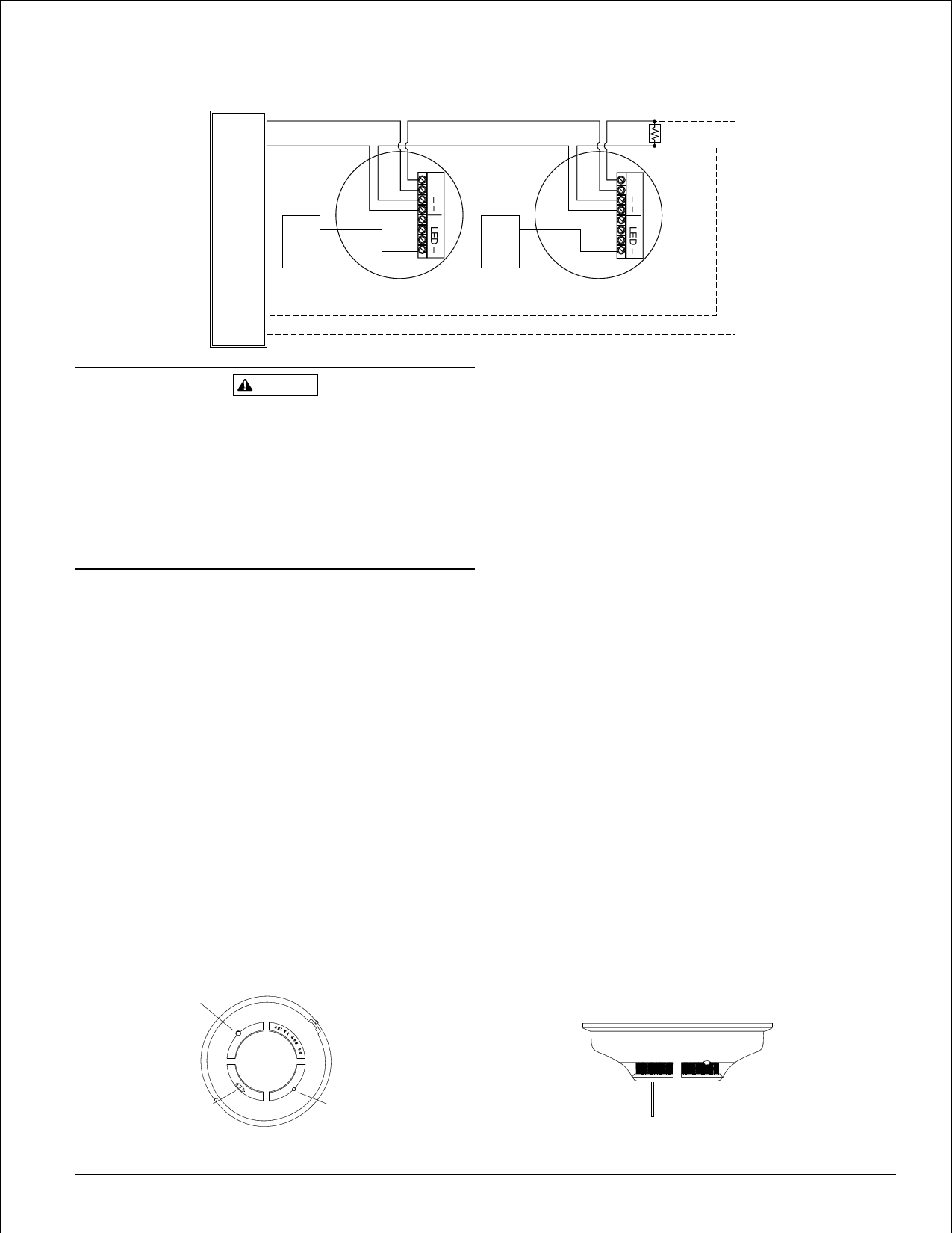
Figure 3. Wiring diagram for the 2100 and 2100T detector:
+
INITIATING
LOOP
–
EOL RESISTOR
SPECIFIED BY
PANEL
MANUFACTURER
+
+
+
+
UL LISTED
+
+
+
+
COMPATIBLE
–
–
CONTROL
PANEL
RA400Z
REMOTE
ANNUNCIATOR
RA400Z
REMOTE
ANNUNCIATOR
OPTIONAL CLASS A WIRING
A78-2331-01
CAUTION
Dust covers are an effective way to limit the entry of dust
into smoke detector sensing chambers. However, they may
not completely prevent airborne dust particles from enter-
ing the detector. Therefore, System Sensor recommends the
removal of detectors before beginning construction or other
dust producing activity. Be sure to remove dust covers from
any sensors that were left in place during construction as
part of returning the system to service.
Testing
NOTE: Before testing, notify the proper authorities that
the smoke detector system is undergoing mainte-
nance and will temporarily be out of service. Dis-
able the zone or system undergoing maintenance
to prevent unwanted alarms.
Detectors must be tested after installation and following
periodic maintenance. Test the 2100 as follows:
A. Test Switch
1. A recessed test switch is located on the detector hous-
ing (See Figure 4).
2. Push and hold the recessed test switch with a 0.1 inch
maximum diameter tool such as an allen wrench or
small screwdriver.
3. The detector’s LED should light within 5 seconds.
B. Test Module (System Sensor Model No. MOD400R).
The MOD400R test module can be used with a DMM or
analog voltmeter to check the detector sensitivity as de-
scribed in the test module’s manual.
C. Smoke Entry Test
Hold a smoldering punk stick or cotton wick at the side
of the detector and gently blow smoke through the de-
tector until the unit alarms.
D. Direct Heat Method (Model 2100T only – Hair dryer of
1000-1500 watts).
Direct the heat toward either of the side thermistors.
Hold the heat source about 12 inches from the detector
in order to avoid damage to the plastic. The detector will
reset only after it has had sufficient time to cool and the
power source has been momentarily interrupted.
Both smoke and heat detection testing are recommended
for verifying system protection capability.
A detector that fails to activate with any of the above tests
should first be cleaned as outlined in the MAINTENANCE
section which follows. If the detector still fails to activate, it
should be returned for repair.
Notify the proper authorities the system is back on line.
Figure 4. Top and side views showing position of test switch:
LED
TEST MODULE
SOCKET
D200-54-00
RECESSED TEST
SWITCH
3
PUSH RECESSED
SWITCH WITH A
0.1" MAX. DIAMETER TOOL
I56-710-05
Share Link: 