LB1663(2008) Просмотр технического описания (PDF) - SANYO -> Panasonic
Номер в каталоге
Компоненты Описание
производитель
LB1663 Datasheet PDF : 5 Pages
| |||
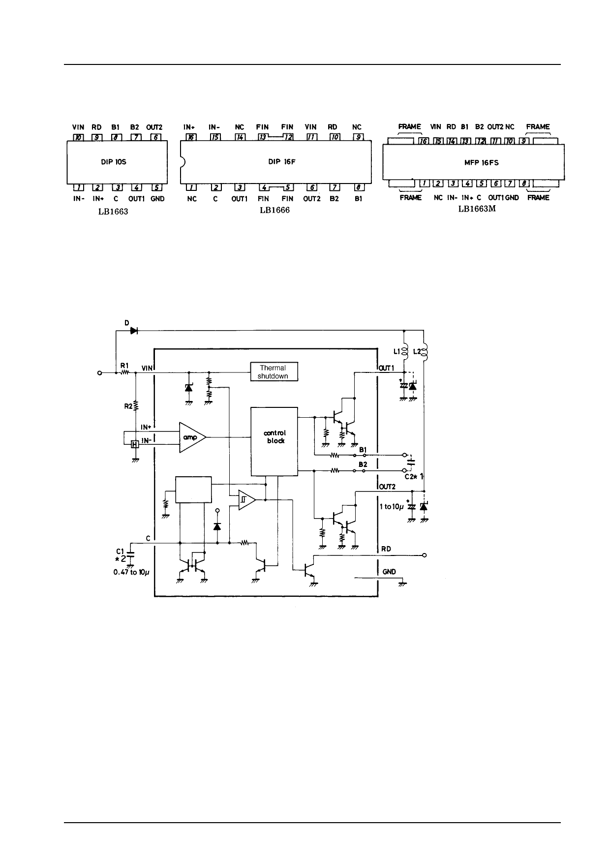
LB1663, 1663M, 1666
Block Diagram and Sample Application Circuit
D
R1 VIN
R2
IN+
H
IN-
amp
Constant
current
circuit
C
C1
*2
0.47 to 10μF
thermal
shut down
Control
block
L1 L2
OUT1
+
B1
B2
OUT2 C2*1
+
1 to 10μF
RD
GND
(Note) *1 : Radio noise reduction capacitor : 0.01 to 0.1μF.
*2 : Use a less leaky capacitor.
Output Protection
For C marked with 1μF
Lock detect time
Lock detect time (output on)
Lock detect time (output off)
Approximately 2s
Approximately 1s
Approximately 6s
Pin Functions
Pin name
Function
VIN
IN-
IN+
OUT1
OUT2
RD
A limiting resistor is connected across VCC and VIN to adjust the current flowing into VIN to be 6mA to 50mA, which generates a voltage
(6.7V) on this pin and supplies a regulated voltage to the IC system and a Hall element.
Pins for accepting output from Hall element.
Common-mode input voltage range : 0 to VIN-1.5V
Offset voltage : ±7mV
Output transistors of output pins are Darlington-connected.
External capacitors or Zener diodes must be connected to protect output transistors.
Open collector output. (Drive mode : ‘‘L’’, Stop mode : ‘‘H’’).
B1
B2
C
GND
Base pins for output transistors of Darlington connection.
A capacitor must be connected in an application where radio noise becomes a problem.
Capacitor pin for automatic return function.
When the rotation is stopped by an overload, the voltage on this pin is increased, turning OFF the output.
Automatic return from output ‘‘stop’’ to ‘‘drive’’ occurs by making the load proper. The lock detect time can be set by changing the
capacitor constant.
Ground.
No.2552-4/5
Share Link: 