MN838850 Просмотр технического описания (PDF) - Panasonic Corporation
Номер в каталоге
Компоненты Описание
производитель
MN838850 Datasheet PDF : 26 Pages
| |||
MN838850
Color TFT LCD Driver
s Functional Description (continued)
• Dot inversion drive (continued)
Next we describe dot inversion drive operation.
The symbol "+" here means a voltage that is positive with respect to the voltage on the opposite electrode, and "−" means
a voltage that is negative with respect to the voltage on the opposite electrode.
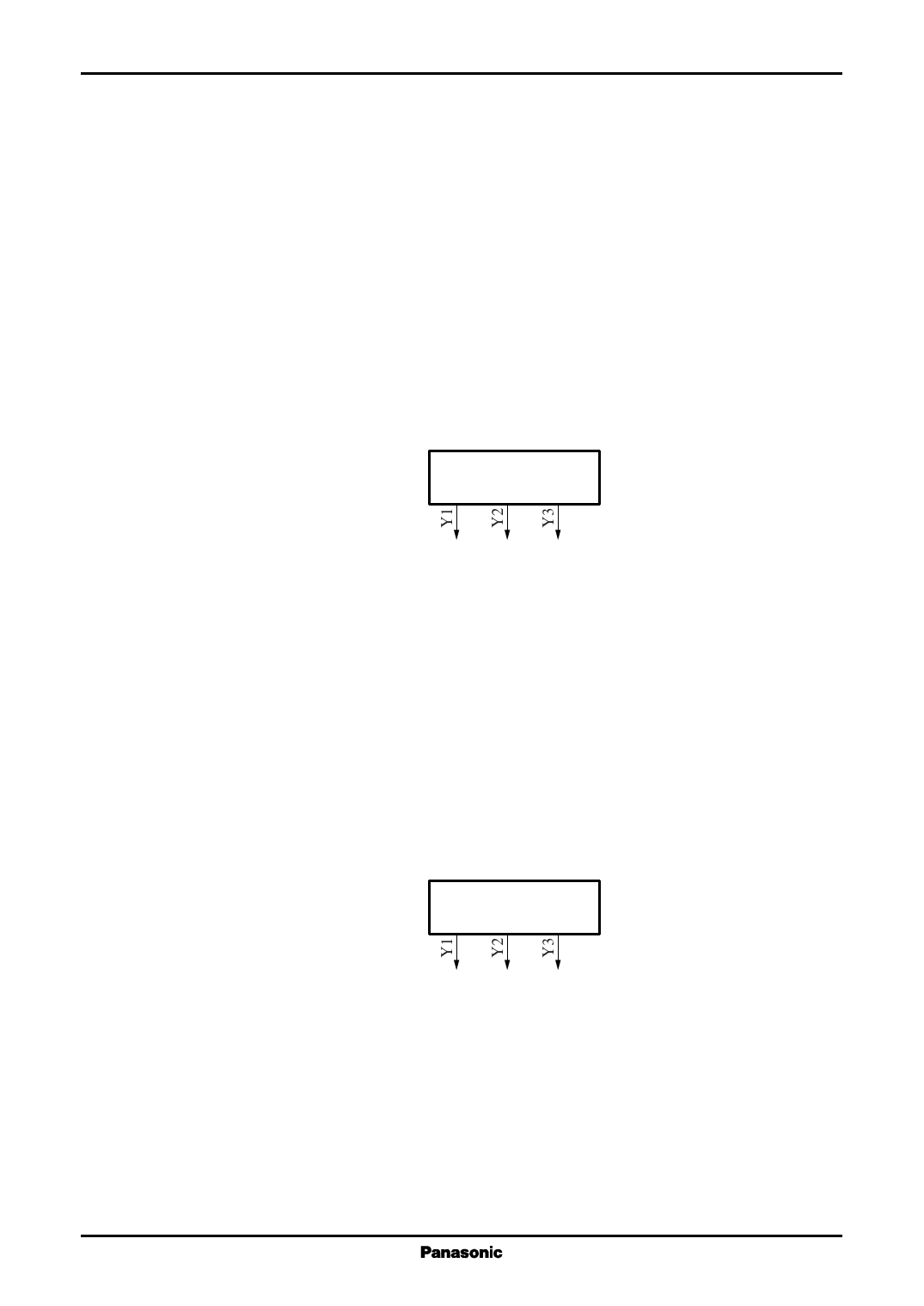
The figure below shows the dot inversion drive operation.
Since POL is low in the first line of the first field, Y1 will be + and Y2 will be −, that is, odd-numbered output pins
will have positive polarity and even-numbered output pins will have negative polarity.
Since POL is switched to high for the second line, odd-numbered output pins will have negative polarity and even-
numbered output pins will have positive polarity.
Thereafter, the polarity of the output voltages is determined by the POL polarity.
In the second field, the POL polarity will be the opposite of what it was for the first field, so the output voltage polarities
will be reversed.
Field 1
Line 1
Line 2
Line 3
Line 4
Field 2
Line 1
Line 2
Line 3
POL
+
−
+
"L"
−
+
−
"H"
+
−
+
"L"
−
+
−
"H"
······
−
+
−
"H"
+
−
+
"L"
−
+
−
"H"
Note that if POL is inverted not every line, but only every field, the output polarities will be as shown below.
Field 1
Line 1
Line 2
Line 3
Field 2
Line 1
Line 2
Line 3
POL
+
−
+
"L"
+
−
+
"L"
+
−
+
"L"
······
−
+
−
"H"
−
+
−
"H"
−
+
−
"H"
8
Share Link: 