BA6901F-E2 Просмотр технического описания (PDF) - ROHM Semiconductor
Номер в каталоге
Компоненты Описание
производитель
BA6901F-E2 Datasheet PDF : 21 Pages
| |||
BA6901F
Datasheet
●Description of operations
1) Lock protection and automatic restart
○CR timer system
Charging and discharging time at LD terminal depends on the capacitor equipped externally on LD terminal. Charging
and discharging time is determined as follows:
TON(charging time) =
TOFF(discharging time)=
C×(VLDCL-VLDCP)
ILDC
C×(VLDCL-VLDCP)
ILDD
C
VLDCL
VLDCP
ILDC
ILDD
: Capacity of capacitor equipped externally on LD terminal
: LD terminal clamping voltage
: LD terminal comparator voltage
: LD terminal charging current
: LD terminal discharging current
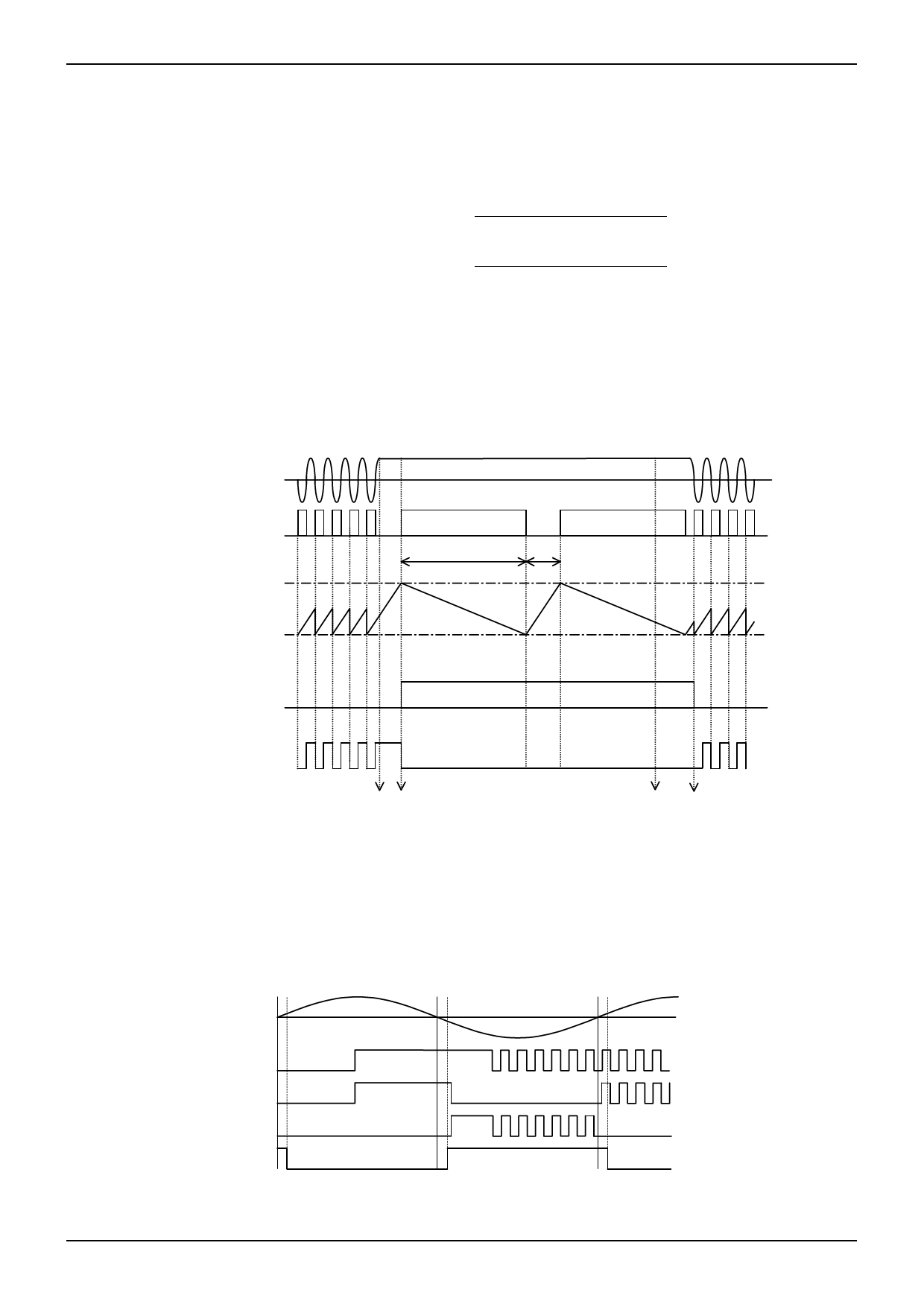
Timing chart of LD terminal is shown in Fig.13.
H-
A1
LD terminal clamping
voltage
LD
LD terminal comparator
voltage
AL
TOFF
Output Tr OFF
TON
ON
HIGH(open collector)
FG
Motor Lock
locking detection
Lock Recovers normal
release operation
Fig.13 Lock protection (CR timer system) timing chart
2) PWM terminal
The signal input to PWM terminal is below L (0.8V or less), output (A1 and A2) turns off. And when it is above H (2.0V
or more), output turns on. PWM terminal is pulled up by resistor (30kΩ:typ.) inside IC. When it is open, the output is in
operating mode.
H+
PWM
A1
A2
FG
Fig.14 Timing chart in PWM control
www.rohm.com
© 2012 ROHM Co., Ltd. All rights reserved.
TSZ22111・15・001
9/17
TSZ02201-0H1H0B100500-1-2
18.DEC.2012 Rev.002
Share Link: 