PM39LV010 Просмотр технического описания (PDF) - PMC-Sierra, Inc
Номер в каталоге
Компоненты Описание
производитель
PM39LV010 Datasheet PDF : 20 Pages
| |||
PMC
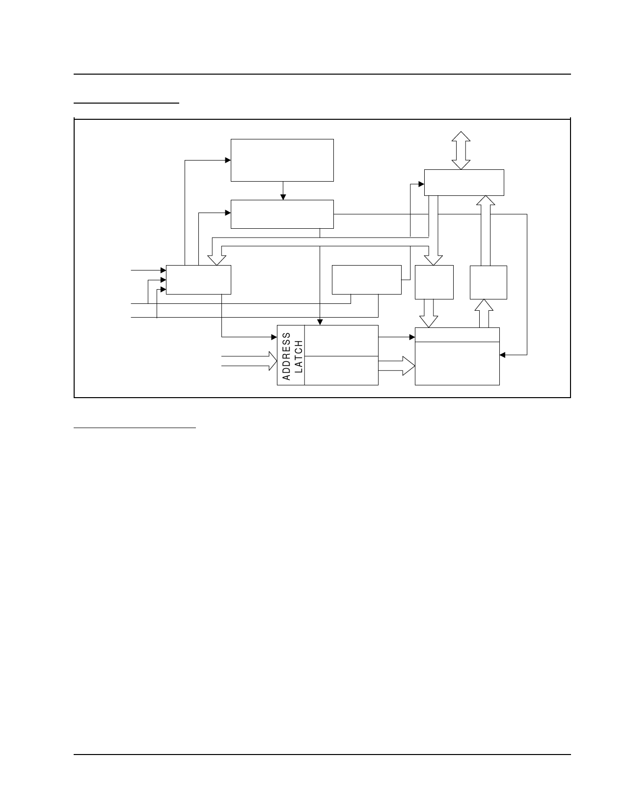
BLOCK DIAGRAM
Pm39LV512 / Pm39LV010 / Pm39LV020 / Pm39LV040
ERASE/PROGRAM
VOLTAGE
GENERATOR
HIGH VOLTAGE
SWITCH
I/O0-I/O7
I/O BUFFERS
WE#
CE#
OE#
COMMAND
REGISTER
A0-AMS
CE,OE LOGIC
DATA
LATCH
SENSE
AMP
Y-DECODER
X-DECODER
Y-GATING
MEMORY
ARRAY
DEVICE OPERATION
READ OPERATION
BYTE PROGRAMMING
The access of Pm39LV512/010/020/040 are similar to
EPROM. To read data, three control functions must be
satisfied:
• CE# is the chip enable and should be pulled low
( VIL ).
• OE# is the output enable and should be pulled
low ( VIL).
• WE# is the write enable and should remains high
( VIH ).
PRODUCT IDENTIFICATION
The programming is a four-bus-cycle operation and the
data is programmed into the devices (to a logical “0”) on
a byte-by-byte basis. See Table 3 for Software Com-
mand Definition. A program operation is activated by writ-
ing the three-byte command sequence followed by pro-
gram address and one byte of program data into the
devices. The addresses are latched on the falling edge
of WE# or CE# whichever occurs later, and the data are
latched on the rising edge of WE# or CE# whichever
occurs first. The internal control logic automatically
handles the internal programming voltages and timing.
The product identification mode can be used to identify
the manufacturer and the device through hardware or
software read ID operation. See Table 1 for PMC Manu-
facturer ID and Device ID. The hardware ID mode is acti-
vated by applying a 12.0 Volt on A9 pin, typically used
by an external programmer for selecting the right pro-
gramming algorithm for the devices. Refer to Table 2 for
Bus Operation Modes. The software ID mode is acti-
vated by a three-bus-cycle command. See Table 3 for
Software Command Definition.
A data “0” can not be programmed back to a “1”. Only
erase operation can convert the “0”s to “1”s. The Data#
Polling on I/O7 or Toggle Bit on I/O6 can be used to
detect the progress or completion of a program cycle.
Programmable Microelectronics Corp.
5
Issue Date: December, 2003 Rev: 1.2
Share Link: 