PM2002DP(2000) Просмотр технического описания (PDF) - South African Micro Electronic Systems
Номер в каталоге
Компоненты Описание
производитель
PM2002DP Datasheet PDF : 10 Pages
| |||
PM2002DP
sames
MODULE SETUP
The PM2002DP module is setup for use with the SA2002D integrated circuit. Resistor values used on the module are calculated for
rated conditions of 80A/220V.
Vdd
P4
Vss
Vdd
J11
P5
Vss
Vdd
J12
P6
Vss
Vdd
J13
P7
Vss
J14 P8
Vdd
P9
Vss
J15 P10
J3
IIN
IIP
Vref
R2
R1
R0
FAST
Vdd
CNF
NC
AGND
IVP
DIRI
DIRO
SA2002D NC
MON
Vss
LED
MOP
NC
P18
P17
P16
P15
P14
P13
P12
P11
J4
Vdd
J2
Vss
J1
JP3 Vss
1
2
J6
654321.1
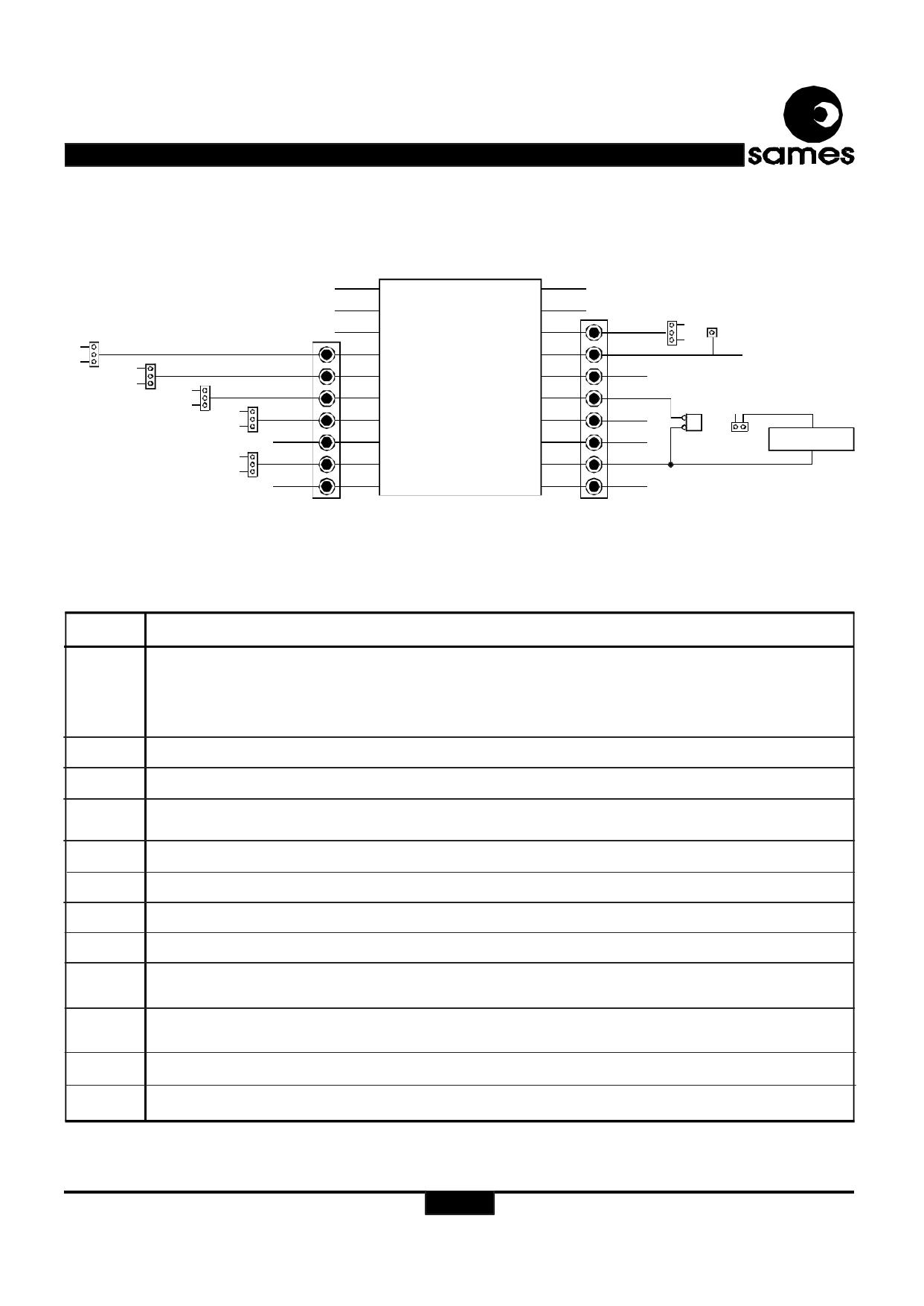
Figure 2: Jumper schematic, digital IO’s
Name
Function Description
J1
J2
J3 and J4
J1 is used to select the energy direction ( DIRI pin). The three options available are:
P18 connected to Vdd - Negative energy measurement
P18 connected to Vss - Positive energy measurement
P18 connected to J2 (P17) - Bi-directional energy measurement
P18 should not be left floating and must be connected to one of the options described above.
J2 is only used to select bi-directional energy measurement when connected to P18
These are test points placed next to the digital pins of the SA2002E
J5
Not fitted This is the current sense input ground. If a current transformer is used for current sensing the two
pins of J5 must be connected.
J6
Connects the impulse to VSS. If a stepper motor is connected to JP3 then J6 should be left open.
J7
J8
J9
J11, J12
and J13
J14
J15
Analog ground test point (see figure 1)
Positive supply test point (Vdd) (see figure 1)
Negative supply test point (Vss) (see figure 1)
Used to select the R2, R1 and R0 pins of the SA2002D for the various rated conditions. Refer to table 1 for the
possible settings
Used to select fast calibration mode. Connecting P7 to Vdd selects fast calibration mode. For normal operation
P7 must be connected to Vss
Used to select between normal and configure / test modes. For normal operation connect P9 to Vss.
J16
Used to select between 220V and 110V mains systems (See figure 3). Leave open for 220V mains.
Table 3: Jumper settings for various device options
http://www.sames.co.za
2/10
Share Link: 