MAX8862 Просмотр технического описания (PDF) - Maxim Integrated
Номер в каталоге
Компоненты Описание
производитель
MAX8862 Datasheet PDF : 12 Pages
| |||
Low-Cost, Low-Dropout, Dual Linear Regulator
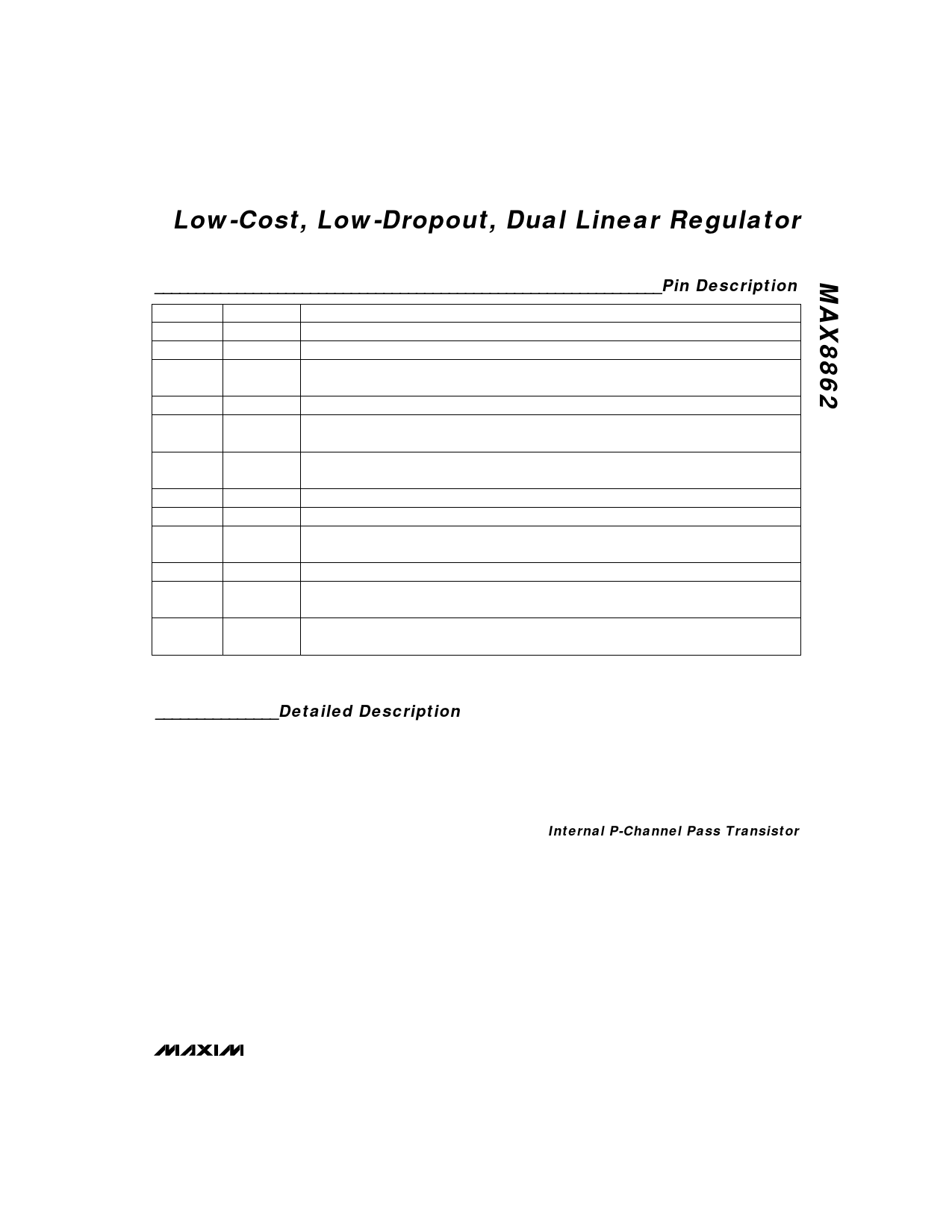
______________________________________________________________Pin Description
PIN
1
2
3
4, 5, 12, 13
6
NAME
IN1
SHDN1
PWROK1
GND
OUT2
FUNCTION
Main Regulator Supply Input (2.5V to 11.5V). Bypass with a 1µF, low-ESR capacitor to GND.
Main Regulator Shutdown Input. A logic low turns off the main regulator and power-good comparator.
Power-Good Output. This open-drain output is low when VOUT1 is out of regulation (VOUT1 is 4%
lower than its nominal value).
Ground. Connect to a ground plane to maximize thermal dissipation.
Secondary Regulator Output. Bypass with a 2.2µF low-ESR (< 0.5Ω) capacitor to GND. To improve
load-transient response and noise performance, use a higher-value, lower-ESR capacitor.
7
8, 16
9
10
11
14
SET2
N.C.
IN2
SHDN2
REF2
OUT1
OUT2 Voltage-Set Input. Connect to GND for the factory-preset output voltage. Connect to a resistive
divider from OUT2 to GND for adjustable output voltage.
No connect. There is no internal connection to this pin.
Secondary Regulator Supply Input (2.5V to 11.5V). Bypass with a 1µF, low-ESR capacitor to GND.
Secondary Regulator Shutdown Input. A logic-low input turns off the secondary regulator and the
reference.
Secondary Reference Output. Bypass with a 0.1µF capacitor to GND.
Main Regulator Output. Bypass with a 3.3µF, low-ESR (< 0.5Ω) capacitor to GND. To improve load-
transient response and noise performance, use a higher-value, lower-ESR capacitor.
15
SET1
OUT1 Voltage Set Input. Connect to GND for the factory-preset output voltage. Connect to a
resistive divider from OUT1 to GND for adjustable output voltage.
_______________Detailed Description
The MAX8862 features Dual Mode™ operation, allow-
ing a fixed output of 4.95V (L), 3.175V (T), or 2.85V (R),
or an adjustable output from 2V to 11V. The regulator’s
outputs, OUT1 and OUT2, supply 250mA and 100mA,
respectively.
The block diagram (Figure 1) shows the contents of
each regulator. Note that the main regulator provides a
power-good indicator, and the secondary regulator’s
reference output voltage is available at REF2.
The 1.25V bandgap reference is connected to the error
amplifier’s inverting input. The error amplifier compares
this reference with the selected feedback voltage and
amplifies the difference. The MOSFET driver reads the
error signal and applies the appropriate drive to the
P-channel transistor. If the feedback voltage is lower
than the reference, the pass transistor’s gate is pulled
lower, allowing more current to pass and increase the
output voltage. If the feedback voltage is too high, the
pass transistor’s gate is pulled up, allowing less current
to pass to the output.
The output voltage is fed back through either an
internal resistor voltage divider connected to OUT1/
OUT2, or an external resistor network connected to
SET1/SET2. The Dual Mode comparator examines
VSET1/VSET2 and selects the feedback path. If this volt-
age is below 40mV, internal feedback is used and the
output voltage is regulated to the factory-preset volt-
age.
Internal P-Channel Pass Transistor
The MAX8862’s P-channel pass transistor provides
several advantages over similar designs using PNP
pass transistors, including longer battery life.
The P-channel MOSFET requires no continuous base
current, thereby reducing quiescent current consider-
ably. PNP regulators normally waste a considerable
amount of current in dropout when the pass transistor
saturates; they also use high base-drive currents under
large loads. The MAX8862 does not suffer from these
problems: it consumes only 200µA of quiescent current
for both regulators under light and heavy loads, as well
as in dropout.
_______________________________________________________________________________________ 7
Share Link: 