MAX6793TP Просмотр технического описания (PDF) - Maxim Integrated
Номер в каталоге
Компоненты Описание
производитель
MAX6793TP
Maxim Integrated

MAX6793TP Datasheet PDF : 25 Pages
| |||
High-Voltage, Micropower, Single/Dual Linear
Regulators with Supervisory Functions
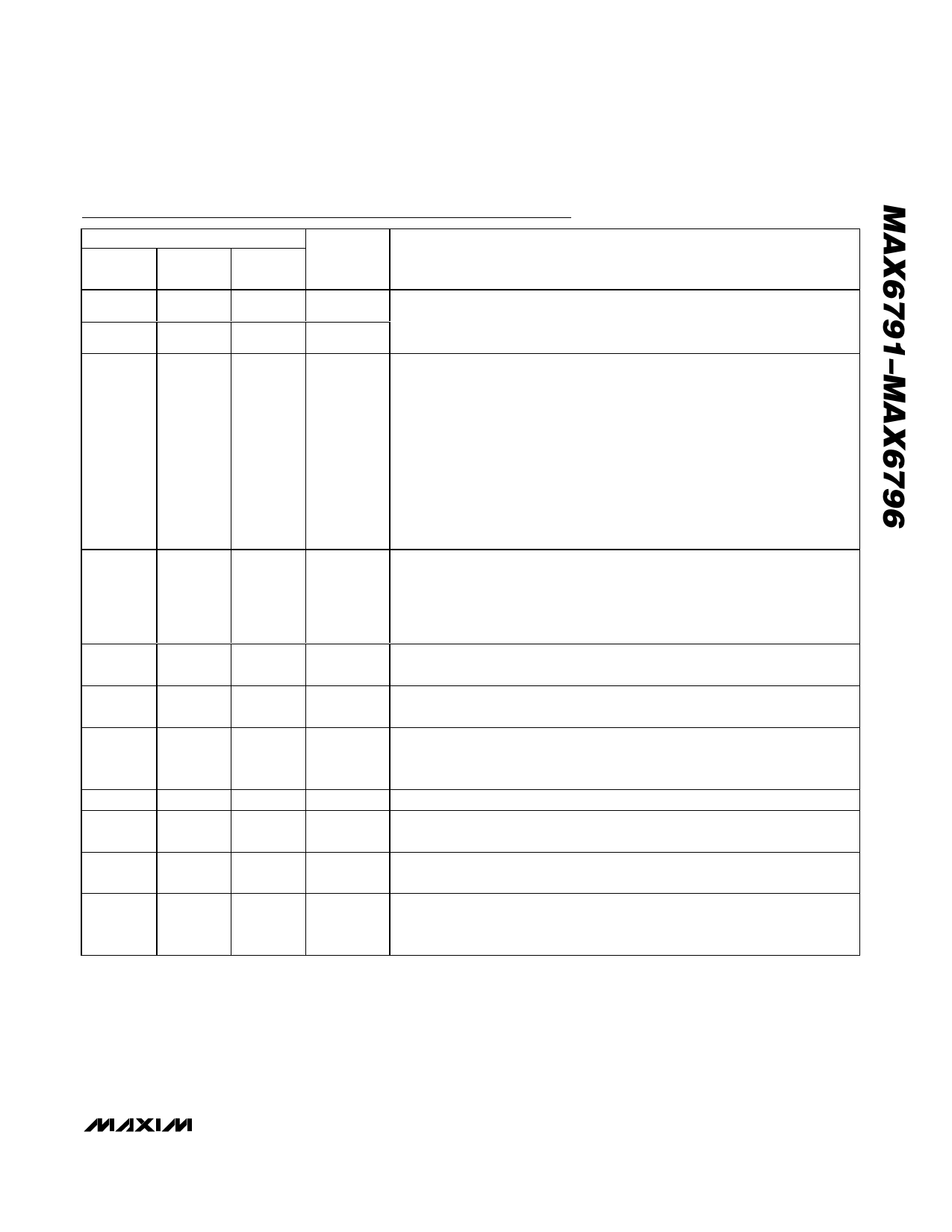
Pin Description (continued)
PIN
MAX6791/ MAX6793/ MAX6795/
MAX6792 MAX6794 MAX6796
NAME
FUNCTION
9
—
—
WDS1 Min/Max Watchdog Logic-Select Input. WDS0 and WDS1 select the watchdog
window ratio or disable the watchdog timer. Drive WDS0 and WDS1 high or
10
—
—
WDS0 low to select the desired ratio, see Table 4.
11
12
13, 14
15
16
17, 18
19
20
—
11
12
13, 14
15
16
17, 18
19
20
9
11
12
—
—
16
17, 18
19
—
9
WDI
HOLD
OUT2
ENABLE2
PFI
IN
GATEP
ENABLE1
WD-DIS
Watchdog Input.
MAX6793–MAX6796: A falling or rising transition must occur on WDI within the
selected watchdog timeout period or a reset pulse occurs. The watchdog timer
clears when a transition occurs on WDI or whenever RESET is asserted. Connect
CSWT to ground to disable the watchdog timer function.
MAX6791/MAX6792: WDI falling and rising transitions within periods shorter than
tWD1 or longer than tWD2 force RESET to assert low for the reset timeout period.
The watchdog timer begins to count after RESET is deasserted. The watchdog
timer clears when a valid transition occurs on WDI or whenever RESET is
asserted. Connect WDS0 high and WDS1 low to disable the watchdog timer
function. See the Watchdog Timer section.
Active-Low Regulator Hold Input. When HOLD is forced low, OUT1/OUT
remains ON even if ENABLE1/ENABLE is pulled low. To shut down the output
of the regulator (OUT/OUT1), release HOLD after ENABLE1/ENABLE is pulled
low. Connect HOLD to OUT1/OUT or leave unconnected if unused. HOLD is
internally connected to OUT/OUT1 through a 2µA current source.
Regulator 2 Output. OUT2 is a fixed +5V output. Connect a 10µF (min)
capacitor from OUT2 to GND.
Active-High Enable Input 2. Drive ENABLE2 high to turn on OUT2. ENABLE2 is
internally connected to ground through a 0.5µA current sink.
Adjustable Power-Fail Comparator Input. Connect PFI to a resistive-divider to
set the desired PFI threshold. The PFI input is referenced to an accurate
1.231V threshold.
Regulator Inputs. Bypass IN with a 1µF capacitor to GND.
pFET Gate Drive. Connect GATEP to the gate of a p-channel MOSFET to
provide low drop reverse-battery voltage protection.
Active-High Enable Input 1. Drive ENABLE1 high to turn on OUT1. ENABLE1 is
internally connected to ground through a 0.5µA current sink.
Watchdog Disable Input. Drive WD-DIS low to disable the watchdog timer.
Drive WD-DIS high or connect to OUT/OUT1 to enable the watchdog timer.
The watchdog timer clears when reset asserts.
______________________________________________________________________________________ 11
Share Link: