MAX3349EA Просмотр технического описания (PDF) - Maxim Integrated
Номер в каталоге
Компоненты Описание
производитель
MAX3349EA Datasheet PDF : 17 Pages
| |||
USB 2.0 Full-Speed Transceiver with UART
Multiplexing Mode
Timing Diagrams (continued)
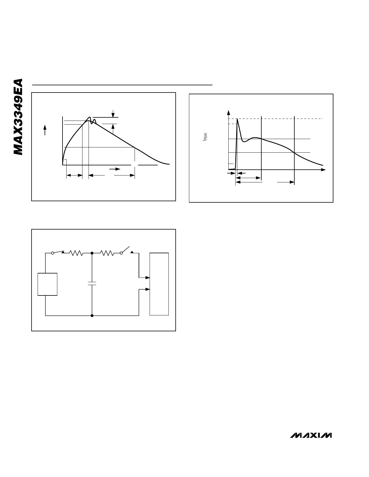
IP 100%
90%
Ir
PEAK-TO-PEAK RINGING
(NOT DRAWN TO SCALE)
I
100%
90%
AMPERES
36.8%
10%
0
0 tRL
TIME
tDL
CURRENT WAVEFORM
10%
tR = 0.7ns to 1ns
30ns
t
60ns
Figure 10. Human Body Model Current Waveform
Figure 12. IEC 61000-4-2 Contact Discharge Model Current
Waveform
RC
50MΩ to 100MΩ
CHARGE-CURRENT-
LIMIT RESISTOR
RD
330Ω
DISCHARGE
RESISTANCE
HIGH-
VOLTAGE
DC
SOURCE
Cs
150pF
STORAGE
CAPACITOR
DEVICE
UNDER
TEST
USB Mode
In USB mode, the MAX3349EA implements a full-speed
(12Mbps) USB interface on D+ and D-, with enumerate
and suspend functions. A differential USB receiver pre-
sents the USB state as a logic-level output RCV (Table
3a). VP/VM are outputs of single-ended USB receivers
when OE is logic-high, allowing detection of single-
ended 0 (SE0) events. When OE is logic-low, VP and
VM serve as inputs to the USB transmitter. Drive sus-
pend input SUS logic-high to force the MAX3349EA into
a low-power operating mode and disable the differen-
tial USB receiver (Table 3b).
Figure 11. IEC61000-4-2 ESD Contact Discharge Test Model
GND with a 0.1µF ceramic capacitor as close to the
device as possible. There are high-impedance resistors
~2MΩ to ground on D+ and D- to prevent floating
nodes when in UART mode and nothing is connected.
Operating Modes
The MAX3349EA operates in either USB mode or
UART mode, depending on the presence or absence
of VBUS. Bus detect output BD is logic-high when a
voltage higher than VTH-VBUS is applied to VBUS, and
logic-low otherwise. The MAX3349EA operates in USB
mode when BD is logic-high, and UART mode when
BD is logic-low.
UART Mode
The MAX3349EA operates in UART mode when BD is
logic-low (VBUS not present). The Rx signal is the out-
put of a single-ended receiver on D+, and the Tx input
is driven out on D-. Signaling voltage thresholds for D+
and D- are determined by VUART, an externally applied
voltage between +2.7V and +3.3V.
Power-Supply Configurations
VL Logic Supply
In both USB and UART modes, the control interface is
powered from VL. The MAX3349EA operates with logic-
side voltage (VL) as low as +1.4V, providing level shift-
ing for lower voltage ASICs and microcontrollers.
10 ______________________________________________________________________________________
Share Link: 