MAX3272 Просмотр технического описания (PDF) - Maxim Integrated
Номер в каталоге
Компоненты Описание
производитель
MAX3272 Datasheet PDF : 14 Pages
| |||
+3.3V, 2.5Gbps Low-Power
Limiting Amplifiers
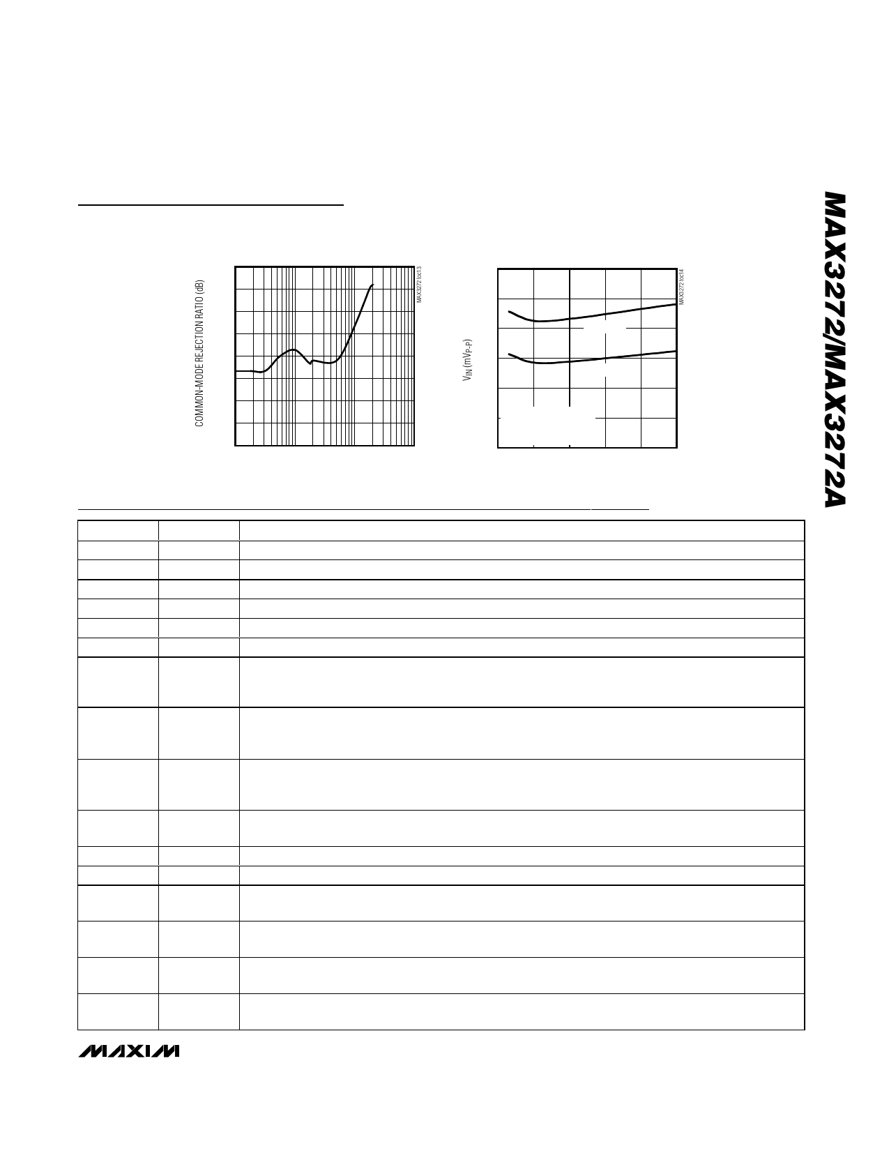
Typical Operating Characteristics (continued)
(VCC = +3.3V, TA = +25°C, unless otherwise noted.)
COMMON-MODE REJECTION RATIO
vs. FREQUENCY
19.0
LOS ASSERT AND DEASSERT LEVELS
vs. DATA RATE
12
18.5
10
18.0
17.5
8
DEASSERT
17.0
16.5
16.0
15.5
15.0
100k
1M
10M
FREQUENCY (Hz)
100M
6
ASSERT
4
2 223 - 1 PRBS PATTERN
RTH = 20kΩ
CIN = 0.1µF
0
0
500 1000 1500 2000 2500
DATA RATE (Mbps)
Pin Description
PIN
1, 4, 17
2
3
5
6, 12, 15, 20
7
NAME
GND
IN+
IN-
TH
VCC
CLOS
8
SQUELCH
9
LOS
10
LOS
11
LEVEL
13
OUT-
14
OUT+
16
OUTPOL
18
CAZ2
19
CAZ1
EP
EXPOSED
PAD
FUNCTION
Supply Ground
Noninverted Input Signal
Inverted Input Signal
Loss-of-Signal Threshold Pin. Resistor to ground sets the LOS threshold.
Power Supply
LOS Time-Constant Capacitor Connection. For SONET applications, CCLOS = 0.01µF is recommended.
Squelch Input. The squelch function is disabled when SQUELCH is not connected or set to TTL low
level. When SQUELCH is set to TTL high level and LOS is asserted, the data outputs (OUT+, OUT-)
are forced to static levels.
Noninverted Loss-of-Signal Output. LOS is asserted TTL high when the signal drops below the assert
threshold set by the TH input. The MAX3272 does not have ESD protection on this pin. The
MAX3272A has ESD protection on this pin.
Inverted Loss-of-Signal Output. LOS is asserted TTL low when the signal drops below the assert
threshold set by the TH input. The MAX3272 does not have ESD protection on this pin. The
MAX3272A has ESD protection on this pin.
Output Current Level. When this pin is not connected, the CML output current is approximately
16mA. When this pin is connected to ground, the output current increases to about 20mA.
Inverted Data Output
Noninverted Data Output
Output Polarity Control Input. Connect to GND for an inversion of polarity through the limiting
amplifier and connect to VCC for normal operation.
Offset-Correction-Loop Capacitor Connection. A capacitor connected between this pin and CAZ1
extends the time constant of the offset correction loop. Typical value of CAZ is 0.1µF.
Offset-Correction-Loop Capacitor Connection. A capacitor connected between this pin and CAZ2
extends the time constant of the offset correction loop. Typical value of CAZ is 0.1µF.
Connect the exposed paddle to board ground for optimal electrical and thermal performance.
_______________________________________________________________________________________ 5
Share Link: 