MAX31782(2010) Просмотр технического описания (PDF) - Maxim Integrated
Номер в каталоге
Компоненты Описание
производитель
MAX31782 Datasheet PDF : 20 Pages
| |||
System Management Microcontroller
ABSOLUTE MAXIMUM RATINGS
VDD to VSS............................................................-0.5V to +5.5V
All Other Pins to VSS except
REG18 and REG25............................... -0.5V to (VDD + 0.5V)*
SCL, SDA, MSDA, MSCL, P6.0–P6.4
Continuous Sink Current..................... 20mA each, 50mA total
P6.0–P6.4 Continuous Source Current....20mA each, 50mA total
Operating Temperature Range........................... -40NC to +85NC
Storage Temperature Range............................ -55NC to +125NC
Lead Temperature (soldering, 10s).................................+260NC
Soldering Temperature (reflow).......................................+260NC
*Subject to not exceeding +5.5V.
Stresses beyond those listed under “Absolute Maximum Ratings” may cause permanent damage to the device. These are stress ratings only, and functional
operation of the device at these or any other conditions beyond those indicated in the operational sections of the specifications is not implied. Exposure to absolute
maximum rating conditions for extended periods may affect device reliability.
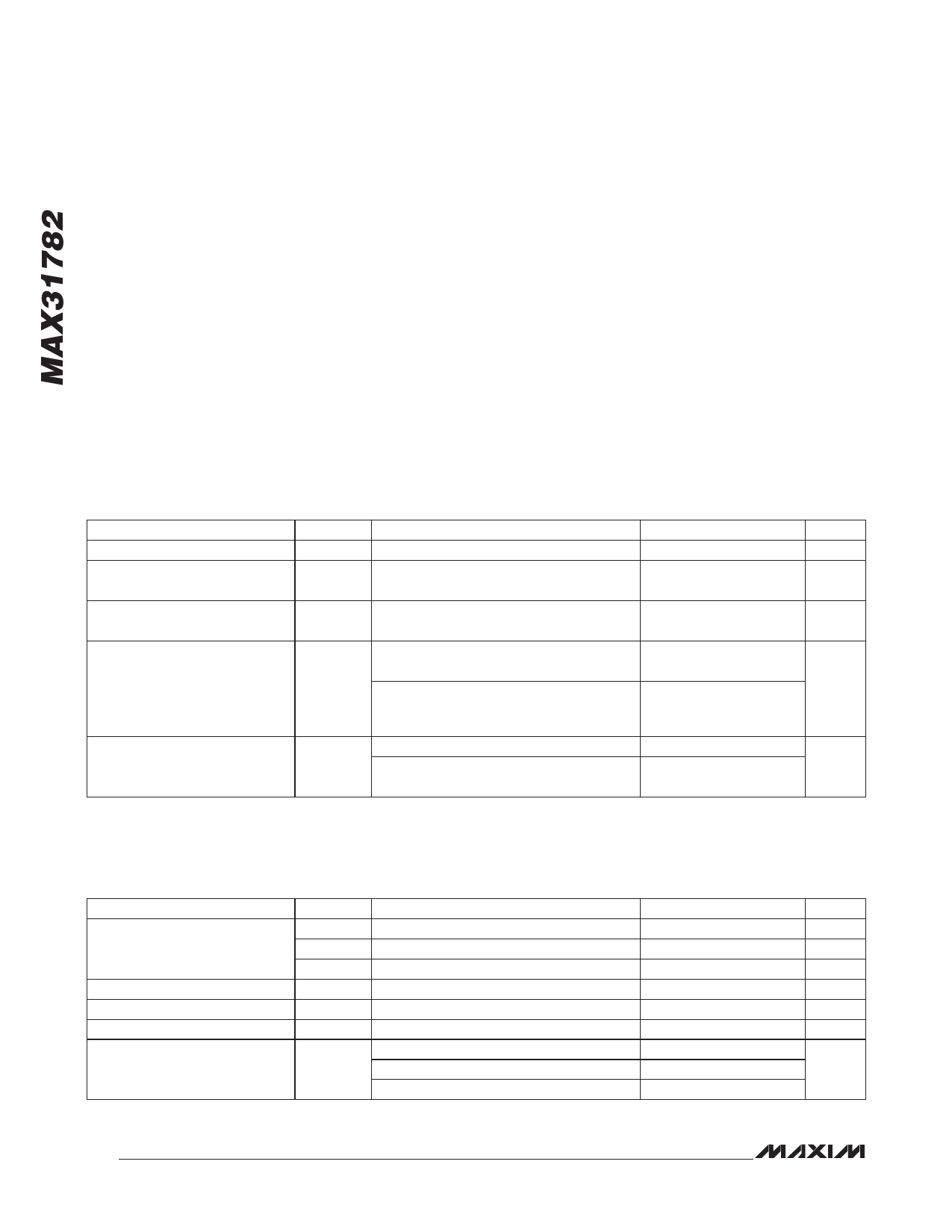
RECOMMENDED OPERATING CONDITIONS
(TA = -40NC to +85NC, unless otherwise noted.)
PARAMETER
VDD Operating Voltage Range
SYMBOL
VDD (Note 1)
CONDITIONS
Input Logic 1
VIH
Input Logic 0
VIL
Input Logic-High: SCL, SDA,
MSDA
Input Logic-Low: SCL, SDA,
MSDA
Input Logic-High: GPIO
(Including SCL, SDA, MSCL, and
MSDA Under Full VDD Range)
Input Logic-Low: GPIO
(Including SCL, SDA, MSCL, and
MSDA Under Full VDD Range)
VI2C_IH
VI2C_IL
VIH1
VIL1
2.7V P VDD P 3.6V (Note 1)
2.7V P VDD P 3.6V (Note 1)
(Note 1)
(Note 1)
MIN
2.7
0.7 x
VDD
-0.3
2.1
-0.5
TYP
MAX
5.5
VDD +
0.3
+0.3 x
VDD
VDD +
0.3
UNITS
V
V
V
V
+0.8
V
0.7 x
VDD
V
0.3 x
VDD
V
DC ELECTRICAL CHARACTERISTICS
(VDD = 2.7V to 5.5V, TA = -40NC to +85NC, unless otherwise noted. Typical values are at VDD = 3.3V, TA = +25NC, unless otherwise
noted.)
PARAMETER
Supply Current
Brownout Voltage
Brownout Hysteresis
Internal System Clock
System Clock Error (Note 3)
SYMBOL
CONDITIONS
ICPU Assuming 100% CPU duty cycle (Note 2)
ISTOP (Note 2)
IPROGRAM
VBO Monitors VDD (Note 1)
VBOH Monitors VDD (Note 1)
fMOSC
Initial tolerance, TA = +25NC, VDD = 5.5V
fERR:MOSC +25NC P TA P +85NC
-40NC P TA P +25NC
MIN TYP MAX UNITS
1.73 2.34
mA
830 1250
µA
7
mA
2.40 2.46 2.55
V
30
mV
4.0
MHz
-1
+1
-2
+1
%
-5.5
+0.6
2
Share Link: 