MAX1627(1996) Просмотр технического описания (PDF) - Maxim Integrated
Номер в каталоге
Компоненты Описание
производитель
MAX1627
(Rev.:1996)
(Rev.:1996)
Maxim Integrated

MAX1627 Datasheet PDF : 16 Pages
| |||
5V/3.3V or Adjustable, 100% Duty-Cycle,
High-Efficiency, Step-Down DC-DC Controllers
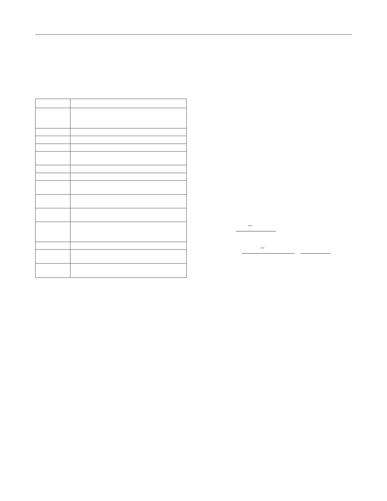
Table 2. Component Suppliers
COMPANY
AVX
USA
Coilcraft
Coiltronics
Dale
International
Rectifier
IRC
Motorola
Nichicon
Nihon
Sanyo
USA
USA
USA
USA
USA
USA
USA
Japan
USA
Japan
USA
Japan
Siliconix
USA
Sprague
Sumida
United
Chemi-Con
USA
USA
Japan
USA
PHONE
(803) 946-0690
or
(800) 282-4975
(847) 639-6400
(516) 241-7876
(605) 668-4131
(310) 322-3331
(512) 992-7900
(602) 303-5454
(847) 843-7500
81-7-5231-8461
(805) 867-2555
81-3-3494-7411
(619) 661-6835
81-7-2070-6306
(408) 988-8000
or
(800) 554-5565
(603) 224-1961
(847) 956-0666
81-3-3607-5111
(714) 255-9500
FAX
(803) 626-3123
(847) 639-1469
(516) 241-9339
(605) 665-1627
(310) 322-3332
(512) 992-3377
(602) 994-6430
(847) 843-2798
81-7-5256-4158
(805) 867-2698
81-3-3494-7414
(619) 661-1055
81-7-2070-1174
(408) 970-3950
(603) 224-1430
(847) 956-0702
81-3-3607-5144
(714) 255-9400
Diode Selection
The MAX1626/MAX1627’s high switching frequency
demands a high-speed rectifier. Schottky diodes, such
as the 1N5817–1N5822 family or surface-mount equiva-
lents, are recommended. Ultra-high-speed rectifiers
with reverse recovery times around 50ns or faster, such
as the MUR series, are acceptable. Make sure that the
diode’s peak current rating exceeds the peak current
limit set by RSENSE, and that its breakdown voltage
exceeds V+. Schottky diodes are preferred for heavy
loads due to their low forward voltage, especially in
low-voltage applications. For high-temperature applica-
tions, some Schottky diodes may be inadequate due to
their high leakage currents. In such cases, ultra-high-
speed rectifiers are recommended, although a Schottky
diode with a higher reverse voltage rating can often
provide acceptable performance.
Capacitor Selection
Choose filter capacitors to service input and output
peak currents with acceptable voltage ripple.
Equivalent series resistance (ESR) in the capacitor is a
major contributor to output ripple, so low-ESR capaci-
tors are recommended. Sanyo OS-CON capacitors are
best, and low-ESR tantalum capacitors are second
best. Low-ESR aluminum electrolytic capacitors are tol-
erable, but do not use standard aluminum electrolytic
capacitors.
Voltage ripple is the sum of contributions from ESR and
the capacitor value:
VRIPPLE ≈ VRIPPLE,ESR + VRIPPLE,C
To simplify selection, assume initially that two-thirds of
the ripple results from ESR and one-third results from
capacitor value. Voltage ripple as a consequence of
ESR is approximated by:
VRIPPLE,ESR ≈ (RESR)(IPEAK)
Estimate input and output capacitor values for given
voltage ripple as follows:
CIN
=
1
2
LI2∆L
VRIPPLE,CINVIN
COUT
=
1
2
LI2∆L
VRIPPLE,COUTVOUT
VIN
VIN
− VOUT
where I∆L is the change in inductor current (around
0.5IPEAK under moderate loads).
These equations are suitable for initial capacitor selec-
tion; final values should be set by testing a prototype or
evaluation kit. When using tantalum capacitors, use
good soldering practices to prevent excessive heat
from damaging the devices and increasing their ESR.
Also, ensure that the tantalum capacitors’ surge-current
ratings exceed the start-up inrush and peak switching
currents.
Pursuing output ripple lower than the error compara-
tor’s hysteresis (0.5% of the output voltage) is not prac-
tical, since the MAX1626/MAX1627 will switch as
needed, until the output voltage crosses the hysteresis
threshold. Choose an output capacitor with a working
voltage rating higher than the output voltage.
The input filter capacitor reduces peak currents drawn
from the power source and reduces noise and voltage
ripple on V+ and CS, caused by the circuit’s switching
action. Use a low-ESR capacitor. Two smaller-value
low-ESR capacitors can be connected in parallel for
lower cost. Choose input capacitors with working volt-
age ratings higher than the maximum input voltage.
Place a surface-mount ceramic capacitor very close to
V+ and GND, as shown in Figure 7. This capacitor
bypasses the MAX1626/MAX1627, and prevents spikes
and ringing on the power source from obscuring the
______________________________________________________________________________________ 11
Share Link: