L6370 Просмотр технического описания (PDF) - STMicroelectronics
Номер в каталоге
Компоненты Описание
производитель
L6370 Datasheet PDF : 10 Pages
| |||
L6370
ELECTRICAL CHARACTERISTICS (continued)
Symbol
Voth1
Voth2
Vohys
Iosd
Vosd
Ioslk
Vdgl
Id glk
Parameter
Output Status Threshold 1
Voltage
Output Status Threshold 2
Voltage
Output Status Threshold
Hysteresis
Output Status Source Current
Active Output Status Driver
Drop Voltage
Output Status Driver Leakage
Current
Diagnostic Drop Voltage
Diagnostic Leakage Current
Test Condition
(See fig. 1)
(See fig. 1)
(See fig. 1)
Vout > Voth1 ; Vos = 2.5V
Vs – Vos ; Ios = 2mA
Tamb = 0 to +85°C
Vout < Voth2 ; Vos = 0V
VS = 9.5 to 35V
D1 / D2 = L ; Idiag = 0.5mA
D1 / D2 = L ; Idiag = 3mA
D1 / D2 =H ; 0 < Vdg < Vs
VS = 9.5 to 35V
SOURCE DRAIN NDMOS DIODE
Vfsd
Forward On Voltage
Ifp
Forward Peak Current
trr
Reverse Recovery Time
tfr
Forward Recovery Time
@ Ifsd = 2.5A
t = 10ms; d = 20%
If = 2.5A di/dt = 25A/µs
THERMAL CHARACTERISTICS
Θ Lim Junction Temp. Protect.
ΘTH
Thermal Hysteresis
Note Vil < 0.8V, Vih > 2V @ (V+In > V–In)
AC OPERATION (pin numbering referred to Multiwatt package)
Min. Typ. Max. Unit
4.5
5
5.5
V
4
4.5
5.0
V
300 500 700 mV
2
4
mA
1.5
3
V
25
µA
40
mV
250
mV
5
µA
1
1.5
V
6
A
200
ns
100
ns
135 150
°C
20
°C
Symbol
tr - tf
td
dV/dt
tON
tOFF
fmax
Pin
9 vs 4
9 vs 3
9, 11
7
Parameter
Rise or Fall Time
Delay Time
Slew Rate (Rise and Fall Edge)
On time during Short Circuit
Condition
Of time during hort Circuit
Condition
Maximum Operating
Frequency
Test Condition
VS = 24V; RI = 70Ω; Rl to
ground
50pF <CDON < 2nF
Min.
0.7
Typ.
20
5
1
1.28
Max.
1.5
Unit
µs
µs
V/µs
µs/pF
64
tON
25
KHz
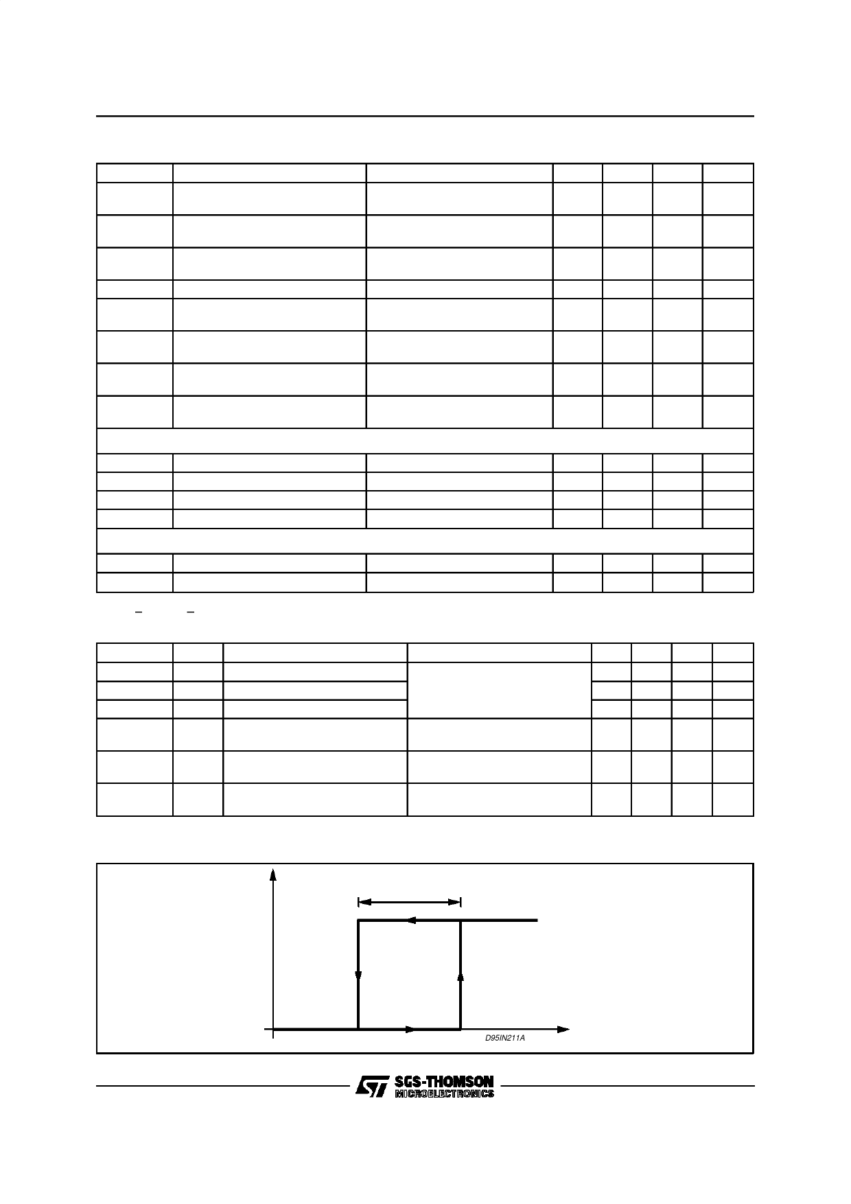
Figure 1: Output Status Hysteresis
Vshys
4/10
Voth2
Voth1 D95IN211A
VOUT
Share Link: 