LTC1150MJ8(RevB) –Я—А–Њ—Б–Љ–Њ—В—А —В–µ—Е–љ–Є—З–µ—Б–Ї–Њ–≥–Њ –Њ–њ–Є—Б–∞–љ–Є—П (PDF) - Linear Technology
–Э–Њ–Љ–µ—А –≤ –Ї–∞—В–∞–ї–Њ–≥–µ
–Ъ–Њ–Љ–њ–Њ–љ–µ–љ—В—Л –Ю–њ–Є—Б–∞–љ–Є–µ
–њ—А–Њ–Є–Ј–≤–Њ–і–Є—В–µ–ї—М
LTC1150MJ8
(Rev.:RevB)
(Rev.:RevB)
Linear Technology

LTC1150MJ8 Datasheet PDF : 16 Pages
| |||
LTC1150
APPLICATIO S I FOR ATIO
ACHIEVING PICOAMPERE/MICROVOLT
PERFORMANCE
Picoamperes
In order to realize the picoampere level of accuracy of the
LTC1150, proper care must be exercised. Leakage cur-
rents in circuitry external to the amplifier can significantly
degrade performance. High quality insulation should be
used (e.g., Teflon, Kel-F); cleaning of all insulating sur-
faces to remove fluxes and other residues will probably
be necessaryвАУparticularly for high temperature perfor-
mance. Surface coating may be necessary to provide a
moisture barrier in high humidity environments.
Board leakage can be minimized by encircling the input
connections with a guard ring operated at a potential
close to that of the inputs: in inverting configurations the
guard ring should be tied to ground; in noninverting
connections to the inverting input. Guarding both sides
of the printed circuit board is required. Bulk leakage
reduction depends on the guard ring width.
Microvolts
Thermocouple effects must be considered if the LTC1150вАЩs
ultralow drift is to be fully utilized. Any connection of
dissimilar metals forms a thermoelectric junction produc-
ing an electric potential which varies with temperature
(Seebeck effect). As temperature sensors, thermocouples
exploit this phenomenon to produce useful information.
In low drift amplifier circuits the effect is a primary source
of error.
Connectors, switches, relay contacts, sockets, resistors,
solder, and even copper wire are all candidates for
thermal EMF generation. Junctions of copper wire from
different manufacturers can generate thermal EMFs of
200nV/¬∞CвАФfour times the maximum drift specification
of the LTC1150. The copper/kovar junction, formed when
wire or printed circuit traces contact a package lead, has
a thermal EMF of approximately 35¬µV/¬∞CвАФ700 times the
maximum drift specification of the LTC1150.
Minimizing thermal EMF-induced errors is possible if
judicious attention is given to circuit board layout and
component selection. It is good practice to minimize the
number of junctions in the amplifierвАЩs input signal path.
Avoid connectors, sockets, switches, and relays where
possible. In instances where this is not possible, attempt
to balance the number and type of junctions so that
differential cancellation occurs. Doing this may involve
deliberately introducing junctions to offset unavoidable
junctions.
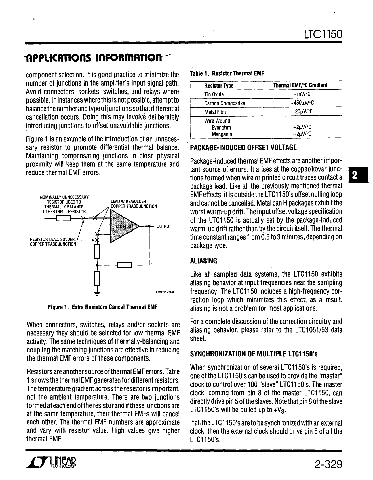
Figure 1 is an example of the introduction of an unneces-
sary resistor to promote differential thermal balance.
Maintaining compensating junctions in close physical
proximity will keep them at the same temperature and
reduce thermal EMF errors.
NOMINALLY UNNECESSARY
RESISTOR USED TO
THERMALLY BALANCE
OTHER INPUT RESISTOR
RESISTOR LEAD, SOLDER,
COPPER TRACE JUNCTION
LEAD WIRE/SOLDER
COPPER TRACE JUNCTION
LTC1150
OUTPUT
LTC1150 вАҐAI01
Figure 1. Extra Resistors Cancel Thermal EMF
When connectors, switches, relays and/or sockets are
necessary, they should be selected for low thermal EMF
activity. The same techniques of thermally-balancing and
coupling the matching junctions are effective in reducing
the thermal EMF errors of these components.
Resistors are another source of thermal EMF errors.
Table 1 shows the thermal EMF generated for different
resistors. The temperature gradient across the resistor is
important, not the ambient temperature. There are two
junctions formed at each end of the resistor and if these
junctions are at the same temperature, their thermal EMFs
will cancel each other. The thermal EMF numbers are
approximate and vary with resistor value. High values give
higher thermal EMF.
1150fb
9
Share Link: