GM1937 Просмотр технического описания (PDF) - Gamma Microelectronics Inc.
Номер в каталоге
Компоненты Описание
производитель
GM1937 Datasheet PDF : 9 Pages
| |||
GM1937
WHITE LED STEP-UP CONVERTER
Application Information – Cont’d
Dimming Control
There are four different types of dimming control:
1. Using a PWM Signal to SHDN Pin
With the PWM signal applied to the CE pin, the GM1937 is turned on or off by the PWM signal. The
LEDs operate at either zero or full current. The average LED current increases proportionally with
the duty cycle of the PWM signal. A 0% duty cycle will turn off the GM1937 and corresponds to zero
LED current. A 100% duty cycle corresponds to full current. The typical frequency range of the PWM
signal is 1kHz to 10kHz. The magnitude of the PWM signal should be higher than the minimum CE
voltage high.
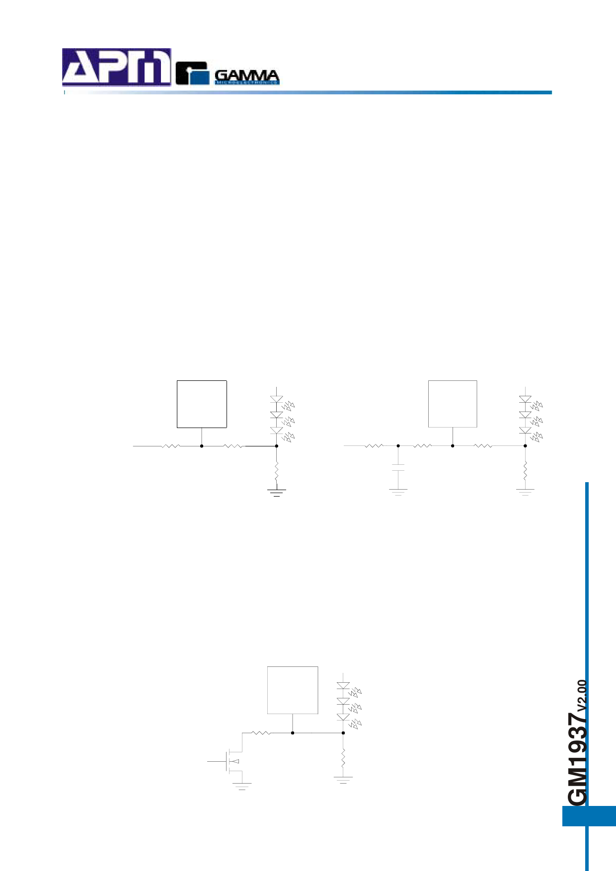
2. Using a DC Voltage
For some applications, the preferred method of brightness control is a variable DC voltage to adjust
the LED current. The dimming control using a DC voltage is shown in Figure 4. As the DC voltage
increases, the voltage drop on R2 increases and the voltage drop on R1 decreases. Thus, the LED
current decreases. The selection of R2 and R3 will make the current from the variable DC source
much smaller than the LED current and much larger than the FB pin bias current. For VDC range
from 0V to 2V, the selection of resistors in Figure 4 gives dimming control of LED current from 0mA
to 15mA.
GM1937
FB
R3
R2
90K
5K
VDC
GM1937
10K
PWM
FB
R3
R2
90K
5K
R1
6.34Ω
0.1µF
R1
6.34Ω
Figure 4. Dimming Control Using a DC Voltage
Figure 5. Dimming Control Using a Filtered
PWM Signal
3. Using a Filtered PWM Signal
The filtered PWM signal can be considered as an adjustable DC voltage. It can be used to replace
the variable DC voltage source in dimming control. The circuit is shown in Figure 5.
4. Using a Logic Signal
For applications that need to adjust the LED current is discrete steps, a logic signal can be used as
shown in Figure 6. R1 sets the minimum LED current (when the NMOS is OFF). RINC sets how
much the LED current increases when the NMOS is turned on. The selection of R1 and RINC can
be found in table 3
GM1937
FB
RINC
Logic Signal
R1
Figure 5. Dimming Control Using a Logic Signal
7
Share Link: 