GM1937 Просмотр технического описания (PDF) - Gamma Microelectronics Inc.
Номер в каталоге
Компоненты Описание
производитель
GM1937 Datasheet PDF : 9 Pages
| |||
GM1937
WHITE LED STEP-UP CONVERTER
Application Information – Cont’d
Diode Selection
Schottky diodes, with their low forward voltage drop and fast reverse recovery, are the ideal choices for
GM1937 applications. The forward voltage drop of a Schottky diode represents the conduction losses in
the diode, while the diode capacitance (CT or CD) represents the switching losses. For diode selection,
both forward voltage drop and diode capacitance need to be considered. Schottky diodes with higher
current ratings usually have lower forward voltage drop and larger diode capacitance, which can cause
significant switching losses at the 1.2MHz switching frequency of the LT1937K. A Schottky diode rated at
100mA to 200mA is sufficient for most GM1937 applications. Some recommended Schottky diodes are
listed in Table 2.
Table 2. Recommended Schottky Diodes
Part Number
Forward
Current (mA)
Voltage Drop (V)
CMDSH-3
100
0.58 @ 100mA
Diode
Capacitance
(pF)
7.0 @10V
Manufacturer
Central
CMDSH2-3
200
0.49 @ 200mA 15 @10V
Central
BAT54
200
0.53 @ 100mA 10 @25V
Zetex
LED Current Control
The LED current is controlled by the feedback resistor (R1 in Figure 1). The feedback reference is 95mV.
The LED current is 95mV/R1. In order to have accurate LED current, precision resistors are preferred
(1% is recommended). The formula and table for R1 selection are shown below.R1 = 95mV/ILED
Table 3. R1 Resistor Value Selection
ILED (mA)
5
R1 (Ω)
19.1
10
9.53
12
7.87
15
6.34
20
4.75
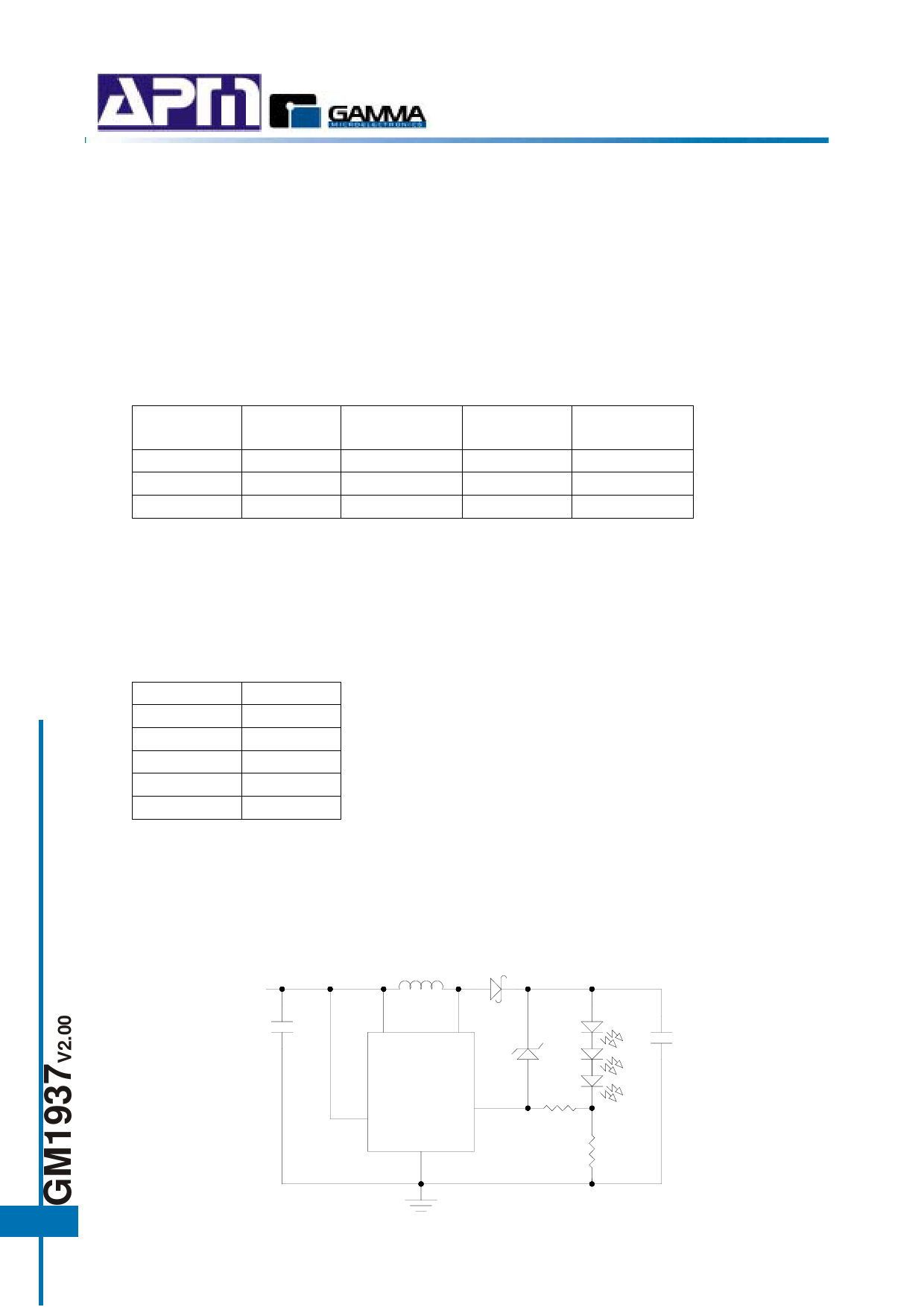
Open-Circuit Protection
In the cases of output open circuit, when the LEDs are disconnected from the circuit or the LEDs fail, the
feedback voltage will be zero. The GM1937 will then switch at a high duty cycle resulting in a high output
voltage, which may cause the SW pin voltage to exceed its maximum 36V rating. A zener diode can be
used at the output to limit the voltage on the SW pin (Figure 3). The zener voltage should be larger than
the maximum forward voltage of the LED string. The current rating of the zener should be larger than
0.1mA.
L
22µH
D
VIN
CIN
1µF
VIN
SW
COUT
0.22µF
GM1937
FB
CE
GND
R2
1K
R1
6.34Ω
6
Figure 3. LED Driver with Open-Circuit Protection
Share Link: 