CY3682(2004) Просмотр технического описания (PDF) - Cypress Semiconductor
Номер в каталоге
Компоненты Описание
производитель
CY3682 Datasheet PDF : 42 Pages
| |||
FO R
FO R
CY7C68001
2.2 Introduction
The EZ-USB SX2™ USB interface device is designed to work
with any external master, such as standard microprocessors,
DSPs, ASICs, and FPGAs to enable USB 2.0 support for any
peripheral design. SX2 has a built-in USB transceiver and
Serial Interface Engine (SIE), along with a command decoder
for sending and receiving USB data. The controller has four
endpoints that share a 4-KB FIFO space for maximum flexi-
bility and throughput, as well as Control Endpoint 0. SX2 has
three address pins and a selectable 8- or 16- bit data bus for
command and data input or output.
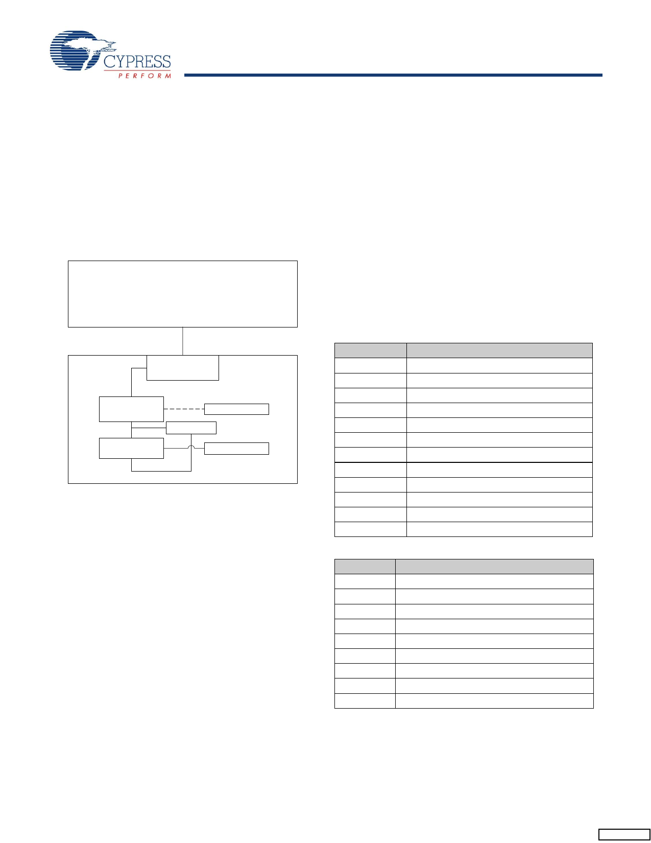
2.3 System Diagram
W indows/US B Capable Host
USB Cable
USB Connection
Cypress
SX2
Device CPU
EEPROM
RAM/ROM
A pplication
Figure 2-2. Example USB System Diagram
3.3 Boot Methods
During the power-up sequence, internal logic of the SX2
checks for the presence of an I2C EEPROM.[1,2] If it finds an
EEPROM, it will boot off the EEPROM. When the presence of
an EEPROM is detected, the SX2 checks the value of first
byte. If the first byte is found to be a 0xC4, the SX2 loads the
next two bytes into the IFCONFIG and POLAR registers,
respectively. If the fourth byte is also 0xC4, the SX2
enumerates using the descriptor in the EEPROM, then signals
to the external master when enumeration is complete via an
ENUMOK interrupt (Section 3.4). If no EEPROM is detected,
the SX2 relies on the external master for the descriptors. Once
this descriptor information is receive from the external master,
the SX2 will connect to the USB bus and enumerate.
3.3.1 EEPROM Organization
The valid sequence of bytes in the EEPROM are displayed
below
Table 3-1. Descriptor Length Set to 0x06:
Default Enumeration
Byte Index
Description
0
0xC4
1
IFCONFIG
2
POLAR
3
0xC4
4
Descriptor Length (LSB):0x06
5
Descriptor Length (MSB): 0x00
6
VID (LSB)
7
VID (MSB)
8
PID (LSB)
9
PID (MSB)
10
DID (LSB)
11
DID (MSB)
3.0 Functional Overview
Table 3-2. Descriptor Length Not Set to 0x06
3.1 USB Signaling Speed
Byte Index
Description
SX2 operates at two of the three rates defined in the Universal
Serial Bus Specification Revision 2.0, dated April 27, 2000:
• Full-speed, with a signaling bit rate of 12 Mbits/s
• High-speed, with a signaling bit rate of 480 Mbits/s.
SX2 does not support the low-speed signaling rate of 1.5
Mbits/s.
0
0xC4
1
IFCONFIG
2
POLAR
3
0xC4
4
Descriptor Length (LSB)
5
Descriptor Length (MSB
3.2 Buses
6
Descriptor[0]
SX2 features:
7
Descriptor[1]
• A selectable 8- or 16-bit bidirectional data bus
8
Descriptor[2]
• An address bus for selecting the FIFO or Command Inter-
face.
Notes:
1. Because there is no direct way to detect which EEPROM type (single or double address) is connected, SX2 uses the EEPROM address pins A2, A1, and A0
to determine whether to send out one or two bytes of address. Single-byte address EEPROMs (24LC01, etc.) should be strapped to address 000 and double-
byte EEPROMs (24LC64, etc.) should be strapped to address 001.
2. The SCL and SDA pins must be pulled up for this detection method to work properly, even if an EEPROM is not connected. Typical pull-up values are 2.2K – 10K
Ohms.
Document #: 38-08013 Rev. *E
Page 2 of 42
Share Link: 