AL1402 Просмотр технического описания (PDF) - Unspecified
Номер в каталоге
Компоненты Описание
производитель
AL1402 Datasheet PDF : 8 Pages
| |||
Application Notes
The clock and data outputs of the AL1402
are undefined after power-up until a proper
data stream is well established at OPDIGIN
(pin 6). The clock outputs may be running
at an uncontrolled frequency. In this case,
the ERROR pin will be high, indicating that
the outputs are invalid. This may be
prevented by applying logic one to FORMAT1
(pin 4) and logic zero to FORMAT0 (pin 3) on
power-up. This resets the AL1402, stopping
the VCO clocks and muting the data output.
The FORMAT pins may then be set to the
value required in your system. Nevertheless
the AL1402 will synchronize and produce
proper outputs when proper and valid
inputs are provided, whether this reset
procedure is used or not.
The AL1402 in Master Mode can also
produce clock outputs running at
uncontrolled frequencies if the digital input
becomes unstable after stable use, due
mostly to poor connection of the optical
cable to the optical connector. If this is
unwanted in the system an external AND
implementation can be used to correct this.
The inverted error pin and the desired
AL1402 output clock are inputs to the AND
and the desired mutable clock is output.
This AND function will mute the selected
AL1402 clock when the error pin is high (i.e.
when unstable input is present at OpDigIn).
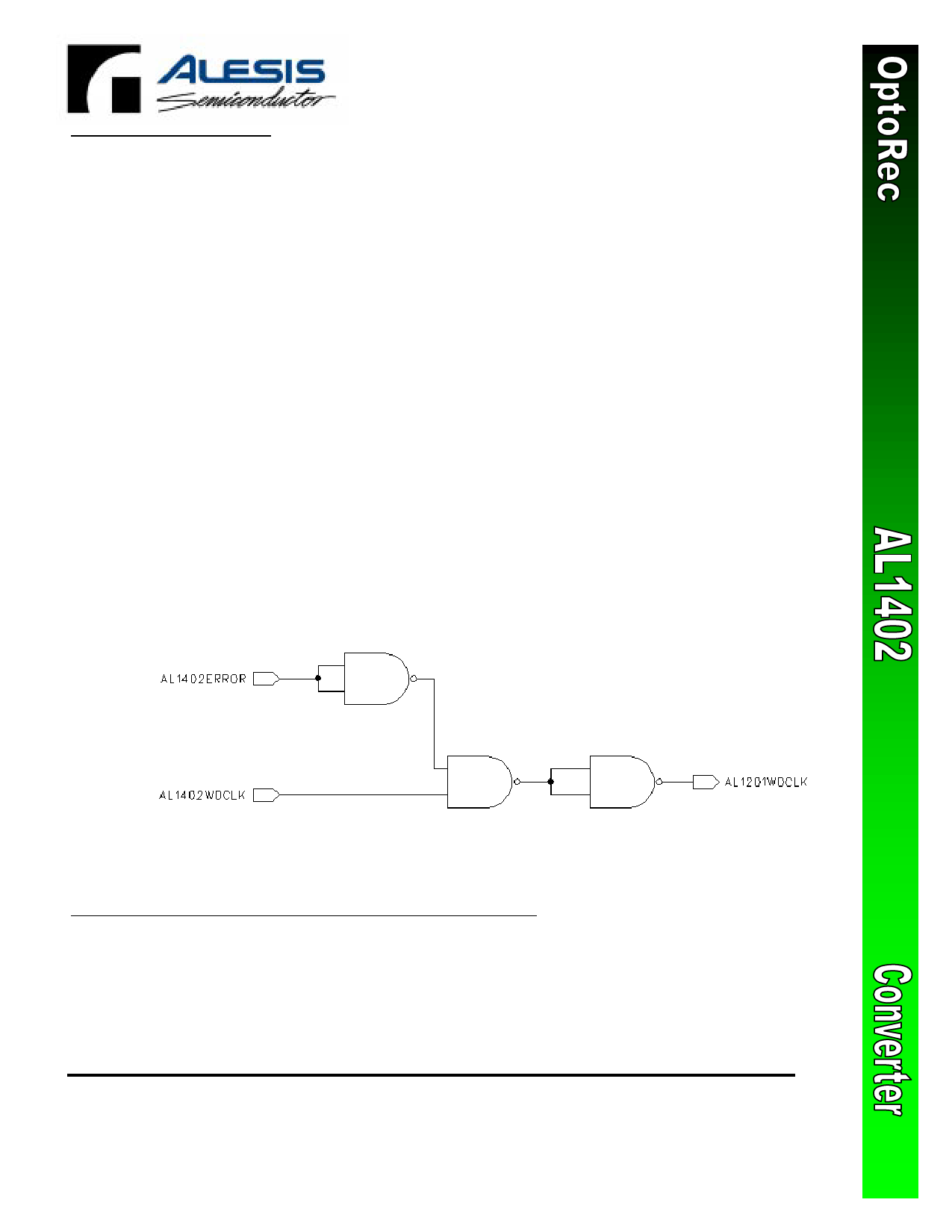
Care should be taken when running the
AL1402 with the AL1201 DAC as the
AL1201 DAC will output noise if the AL1402
WDCLK is at an uncontrolled VCO frequency
that is beyond the AL1201 maximum
frequency. The aforementioned AND
function can be used to select the AL1402
WDCLK to be muted when invalid
OpDigInput is present before proceeding as
the AL1201 WDCLK. See Figure F. with the
AND function implemented with NAND
gates. In place of this circuit the ERROR pin
can be used as a mute select for any audio
output stage muting circuitry that may be
present in the system.
Figure F. AL1402 –AL1201 CLK MUTE CIRCUIT.
Alesis Semiconductor
DS1402-0702
12555 Jefferson Blvd., Suite 285
Los Angeles, CA 90066
Phone (310) 301-0780 Fax (310) 306-1551 www.alesis-semi.com
-7-
Share Link: 