78P7200L Просмотр технического описания (PDF) - TDK Corporation
Номер в каталоге
Компоненты Описание
производитель
78P7200L Datasheet PDF : 24 Pages
| |||
78P7200L
E3/DS3/STS-1
Transceiver
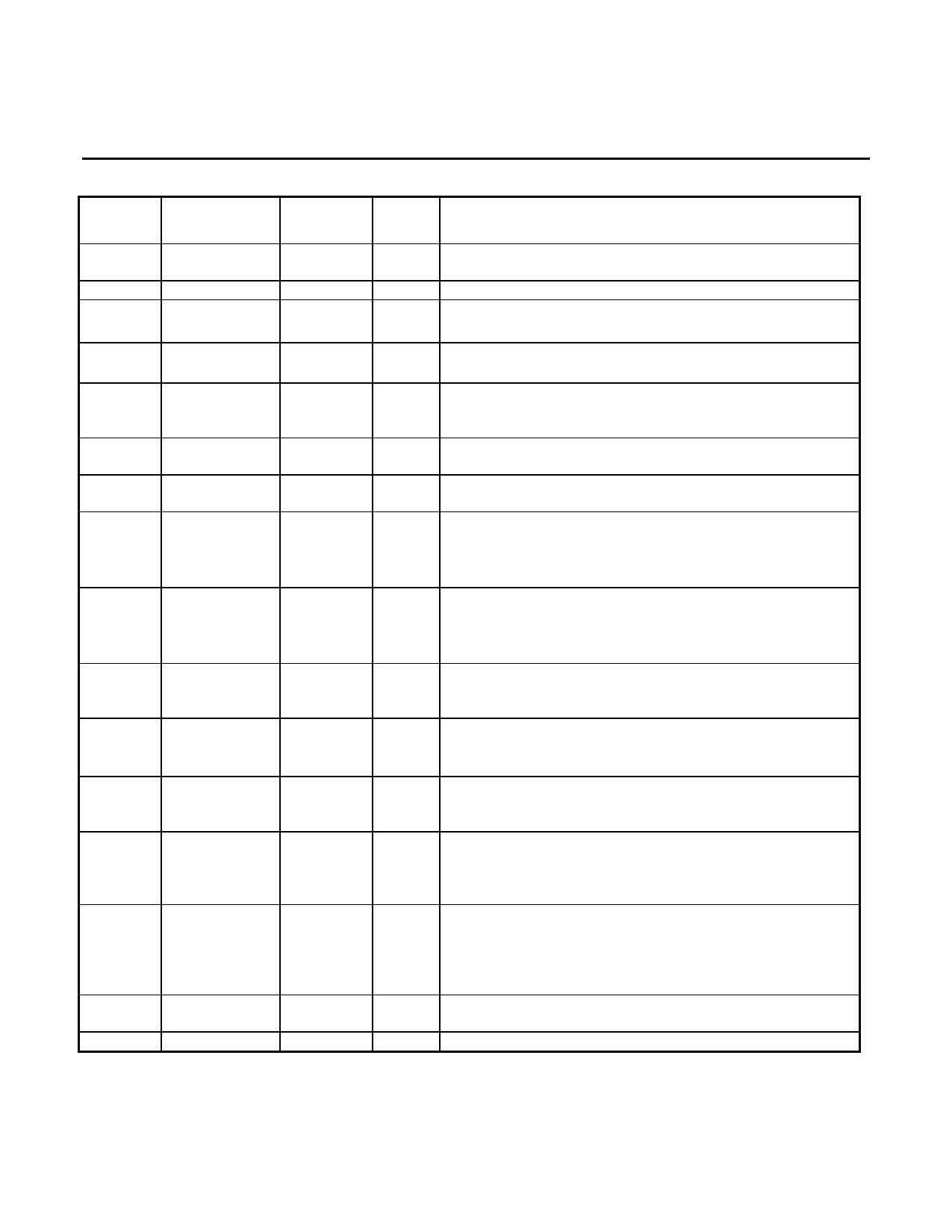
PIN DESCRIPTION: THE 28-PIN PLCC IS COMPATIBLE WITH 78P7200 AND 78P2241
NAME
PIN
PIN
TYPE DESCRIPTION
LIN+
LIN-
RCLK
TQFP
42
44
33
PLCC
1
3
23
I
Line Input: Differential AMI inputs to the chip. Should be
transformer coupled and terminated at 75-ohm resistor.
O Receive Clock: Recovered receive clock.
RPOS/
35
RNRZ
RNEG
34
LOS
39
LOUT+
9
LOUT-
11
TCLK
18
TPOS/
16
TNRZ
25
O Receive Positive Data / NRZ Data: This pin indicates
reception of a positive AMI pulse on the coax cable.
24
O Receive Negative Data: This pin indicates reception of a
negative AMI pulse on the coax.
27
O Loss of Signal: logic low indicates that receiver signal
(LIN±) is below the threshold level
RPOS and RNEG are forced low when LOS=0.
9
O Line Out: Differential AMI Output. Requires a 2:1 center
11
tapped transformer and 301Ω resistor.
16
I
Transmitter Clock Input: This signal is used to latch the
TPOS/TNRZ and TNEG signals into the 78P7200L.
14
I
Transmit Positive Data / Transmit NRZ: A logic one on this
pin generates a positive AMI pulse on the coax. This pin
should not be high at the same time that TNEG is high.
TNEG
17
15
I
Transmit Negative Data: A logic one on this pin generates
a negative AMI pulse on the coax. This pin should not be
high at the same time that TPOS/TNRZ is high.
LBO
E#
TXEN
ICKP
LPBK
VCC
N/C
13
15
22
10
40
5,6,20,
21,37,38
27, 28
12
13
18
10
28
7,17,26
20, 21
I
Line Build-Out, Transmitter: Logic low used with 225ft or
more of cable is used on transmit path. Logic high used
with less than 225ft of cable.
I3 DS3, E3 and STS-1 Select: Set low for E# applications.
Set high for DS3, allow to float for STS-1 operation.
Formerly OPT! on the 78P7200.
I
Transmitter Enable: When high, enables transmitter.
When low, tri-states transmitter drivers, LOUT±. This pin
was called OPT@ on 78P7200.
I3 Invert Clock Polarity: When low, the polarities of RCLK and
TCLK are the same as those on the 78P7200. When set
high, the polarity of TCLK is inverted. When allowed to float,
the polarities of both RCLK and TCLK are inverted.
I3 Loop-back Select: When high, neither loop-back is
activated.
When allowed to float RPOS, RNEG and RCLK are
looped back onto TPOS, TNEG and TCLK. When low,
LOUT± is looped back onto LIN±.
P Power Supply.
No Connect
4
Share Link: 