695D335X0020D2 Просмотр технического описания (PDF) - Vishay Semiconductors
Номер в каталоге
Компоненты Описание
производитель
695D335X0020D2 Datasheet PDF : 22 Pages
| |||
www.vishay.com
695D
Vishay Sprague
Solid Tantalum Chip Capacitors,
TANTAMOUNT™, Conformal Coated
PERFORMANCE CHARACTERISTICS
www.vishay.com/doc?40194
Operating Temperature: -55 °C to +125 °C
(above 85 °C, voltage derating is required)
Capacitance Range: 1.0 μF to 270 μF
Capacitance Tolerance: ± 10 %, ± 20 % standard
Voltage Rating: 4 VDC to 50 VDC
Moisture Sensitivity Level 2a
FEATURES
• Pad compatible with 194D and
MIL-PRF-55365/4 (CWR06)
• 8 mm, 12 mm 16 mm tape to EIA-481 and
reeling per IEC 286-3. 7" [178 mm] standard
13" [330 mm] available
Available
Available
• Terminations: 100 % tin (2) standard,
tin / lead available
• Material categorization:
for definitions of compliance please see
www.vishay.com/doc?99912
Available
Note
* This datasheet provides information about parts that are
RoHS-compliant and / or parts that are non RoHS-compliant. For
example, parts with lead (Pb) terminations are not RoHS-compliant.
Please see the information / tables in this datasheet for details
ORDERING INFORMATION
695D
475
X0
TYPE
CAPACITANCE
CAPACITANCE
TOLERANCE
004
DC VOLTAGE RATING
AT +85 °C
A
2
CASE CODE TERMINATION
T
REEL SIZE AND
PACKAGING
This is expressed in
picofarads. The first
two digits are the
significant figures.
The third is the
number of zeros to
follow.
X0 = ± 20 %
X9 = ± 10 %
This is expressed in volts.
To complete the three-digit
block, zeros precede the
voltage rating. A decimal
point is indicated by an “R”
(6R3 = 6.3 V).
See Ratings
and Case
Codes table
2 = 100 % tin
4 = gold plated
8 = solder plated
(60/40)
Special order
T = tape and reel
7" [178 mm] reel
W = 13" [330 mm] reel
See tape and reel
specifications
Notes
• Preferred tolerance and reel sizes are in bold
• We reserve the right to supply higher voltage ratings and tighter capacitance tolerance capacitors in the same case size
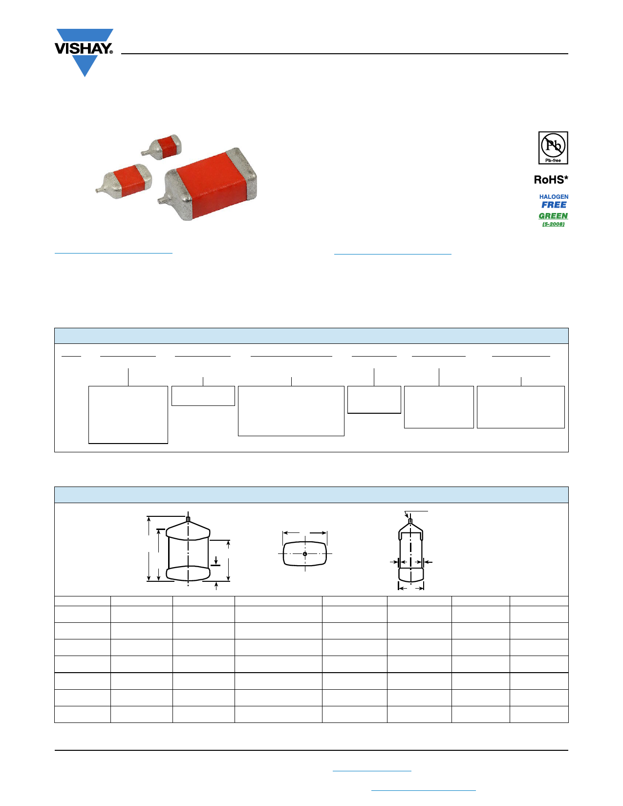
DIMENSIONS in inches [millimeters]
Tantalum wire
nib identifies
L
MAX.
W
anode (+)
terminal
D
B
REF.
A
J
MAX.
J
MAX.
CASE CODE L (MAX.)
D (REF.)
W
H
A
0.134
[3.4]
0.100
[2.54]
0.050 ± 0.015
[1.27 ± 0.38]
0.050 ± 0.015
[1.27 ± 0.38]
B
0.185
[4.7]
0.150
[3.81]
0.050 ± 0.015
[1.27 ± 0.38]
0.050 ± 0.015
[1.27 ± 0.38]
D
0.185
[4.7]
0.140
[3.56]
0.095 ± 0.015
[2.41 ± 0.38]
0.050 ± 0.015
[1.27 ± 0.38]
E
0.236
[6.0]
0.200
[5.08]
0.095 ± 0.015
[2.41 ± 0.38]
0.050 ± 0.015
[1.27 ± 0.38]
F
0.256
[6.5]
0.220
[5.59]
0.135 ± 0.015
[3.43 ± 0.38]
0.070 ± 0.015
[1.78 ± 0.38]
G
0.300
[7.6]
0.260
[6.60]
0.100 ± 0.015
[2.54 ± 0.38]
0.100 ± 0.015
[2.54 ± 0.38]
H
0.303
[7.7]
0.265
[6.73]
0.150 ± 0.015
[3.81 ± 0.38]
0.110 ± 0.015
[2.79 ± 0.38]
Note
• The anode termination (D less B) will be a minimum of 0.25 mm (0.010").
H
A
0.023 ± 0.010
[0.584 ± 0.25]
0.040 ± 0.015
[1.02 ± 0.38]
0.040 ± 0.015
[1.02 ± 0.38]
0.040 ± 0.015
[1.02 ± 0.38]
0.040 ± 0.015
[1.02 ± 0.38]
0.040 ± 0.015
[1.02 ± 0.38]
0.050 ± 0.015
[1.27 ± 0.38]
B
0.067 ± 0.015
[1.70 ± 0.38]
0.120 ± 0.015
[3.05 ± 0.38]
0.110 ± 0.020
[2.79 ± 0.51]
0.170 ± 0.020
[4.32 ± 0.51]
0.185 ± 0.020
[4.70 ± 0.51]
0.220 ± 0.020
[5.59 ± 0.51]
0.220 ± 0.020
[5.59 ± 0.51]
J (MAX.)
0.004
[0.10]
0.004
[0.10]
0.004
[0.10]
0.004
[0.10]
0.004
[0.10]
0.004
[0.10]
0.004
[0.10]
Revision: 17-Jul-2018
1
Document Number: 40038
For technical questions, contact: tantalum@vishay.com
THIS DOCUMENT IS SUBJECT TO CHANGE WITHOUT NOTICE. THE PRODUCTS DESCRIBED HEREIN AND THIS DOCUMENT
ARE SUBJECT TO SPECIFIC DISCLAIMERS, SET FORTH AT www.vishay.com/doc?91000
Share Link: 