KE5BGCA256A Просмотр технического описания (PDF) - KAWASAKI MICROELECTRONICS
Номер в каталоге
Компоненты Описание
производитель
KE5BGCA256A Datasheet PDF : 114 Pages
| |||
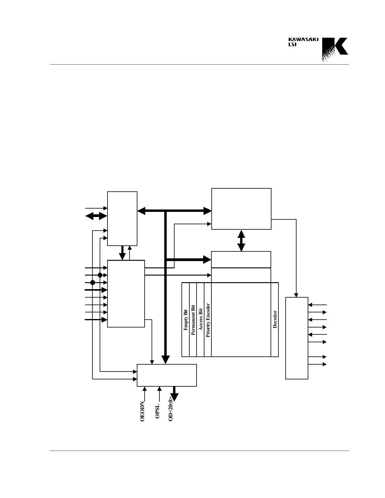
2. Block Diagram
GigabitCAM KE5BGCA256
This device consists of the following blocks as shown.
CPU Bus Control Block
An access to the search key data, commands, or internal regis-
ters are executed through the CPU Bus.
Pipeline Execution Control
This block controls the pipeline operation of this device.
CNTL1/2 Registers
These registers define the mask registers and the input
modes , etc.
OEDATN
DAT<31:0>
CPU
Bus
Control
CNTL1/2 Registers
Memory R/W Registers
SCONF Register
CMP1/2 Registers
HHA/HEA Registers
RSTN
CLK
PHASE
ADD<5:0>
SRCHN
RWN
CEN
MS<3:0>
Pipeline
Execution
Control
MASK Register 0~11
Search Logic
Control Logic
64-bit x 4096
CAM
Output Port Control
Flag
Logic
PHIN
PHON
PMIN
PMON
FLIN
FLON
SHON
SMON
Preliminary
Fig. 2 Block Diagram
2-1
Share Link: 