GL600USB Просмотр технического описания (PDF) - Genesys Logic
Номер в каталоге
Компоненты Описание
производитель
GL600USB Datasheet PDF : 38 Pages
| |||
GL600USB/GL600USB-A/GL600USB-B
4 FUNCTIONAL DESCRIPTION
The Genesys Logic GL600USB microcontroller is optimized for USB 2D/3D/4D mouse. This USB
microcontroller conforms to the low-speed (1.5Mbps) requirements of the USB Specification version 1.1.
The microcontroller is a self-contained unit with an USB SIE, an USB transceiver, an 8-bits RISC-like
microcontroller, a timer, data and program memories. It supports one USB device address and two
endpoints (include endpoint 0).
4.1 MEMORY ORGANIZATION
The memory in the microcontroller is organized into user program memory in program ROM and data
memory in SRAM space.
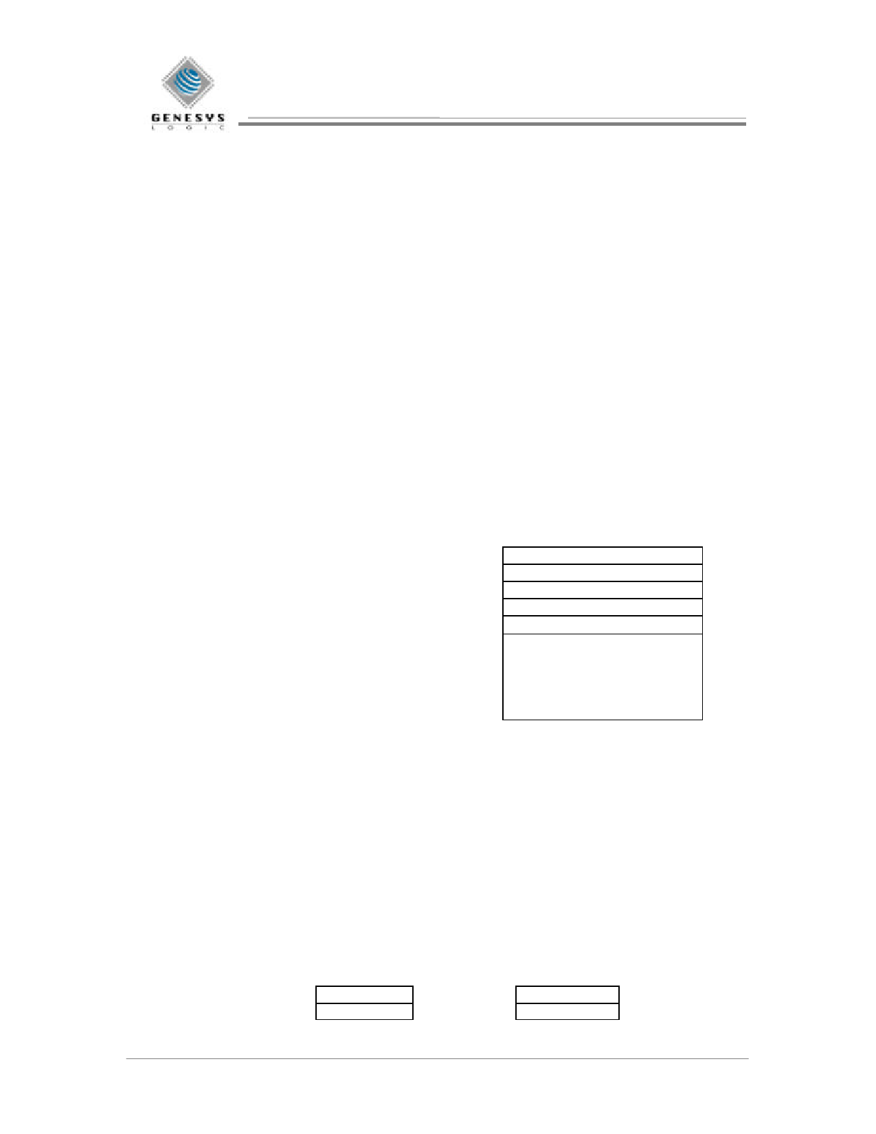
4.1.1 Program Memory Organization
The 11-bit Program Counter (PC) is capable of addressing 2K x 14 of program space. However, the
program space of the GL600USB is 1.75K x 14. The program memory space is divided into two functional
groups: Interrupt Vectors and program code. After a reset, the Program Counter points to location zero of
the program space. After a timer interrupt, the Program Counter points the location 0x0004 of the program
space.
After Reset
→ Address
0x0000 Reset Vector
After Timer Interrupt
→ 0x0004
0x0005
Timer Interrupt Vector
1.75K x 14 ROM
0x06FF
Figure 4-1 Program Memory Space
4.1.2 Data Memory Organization
The data memory is partitioned into two banks which contain the General Purpose Registers, MCU
Function Registers and USB Function Registers. Bit RP0 is the bank select bit.
RP0 (STATUS<5>) = 1 → Bank 1
RP0 (STATUS<5>) = 0 → Bank 0
The lower locations of each Bank are reserved for MCU Function Registers and USB Function Registers.
Above the MCU Function Registers and USB Function Registers are General Purpose Registers
implemented as SRAM. Both Bank 0 and Bank 1 contain MCU Function Registers. USB Function
Registers are located in Bank 0. Some “high use” MCU Function Registers from Bank 0 are mirrored in
Bank 1 for code reduction and quicker access.
Data Memory
Address
00h
01h
INDR
TIMER
Data Memory
Address
80h
81h
INDR
PSCON
10
06/19/2000
Revision 1.3
Share Link: 