PM25LV020-33SC Просмотр технического описания (PDF) - PMC-Sierra, Inc
Номер в каталоге
Компоненты Описание
производитель
PM25LV020-33SC
PMC-Sierra, Inc

PM25LV020-33SC Datasheet PDF : 32 Pages
| |||
PMC
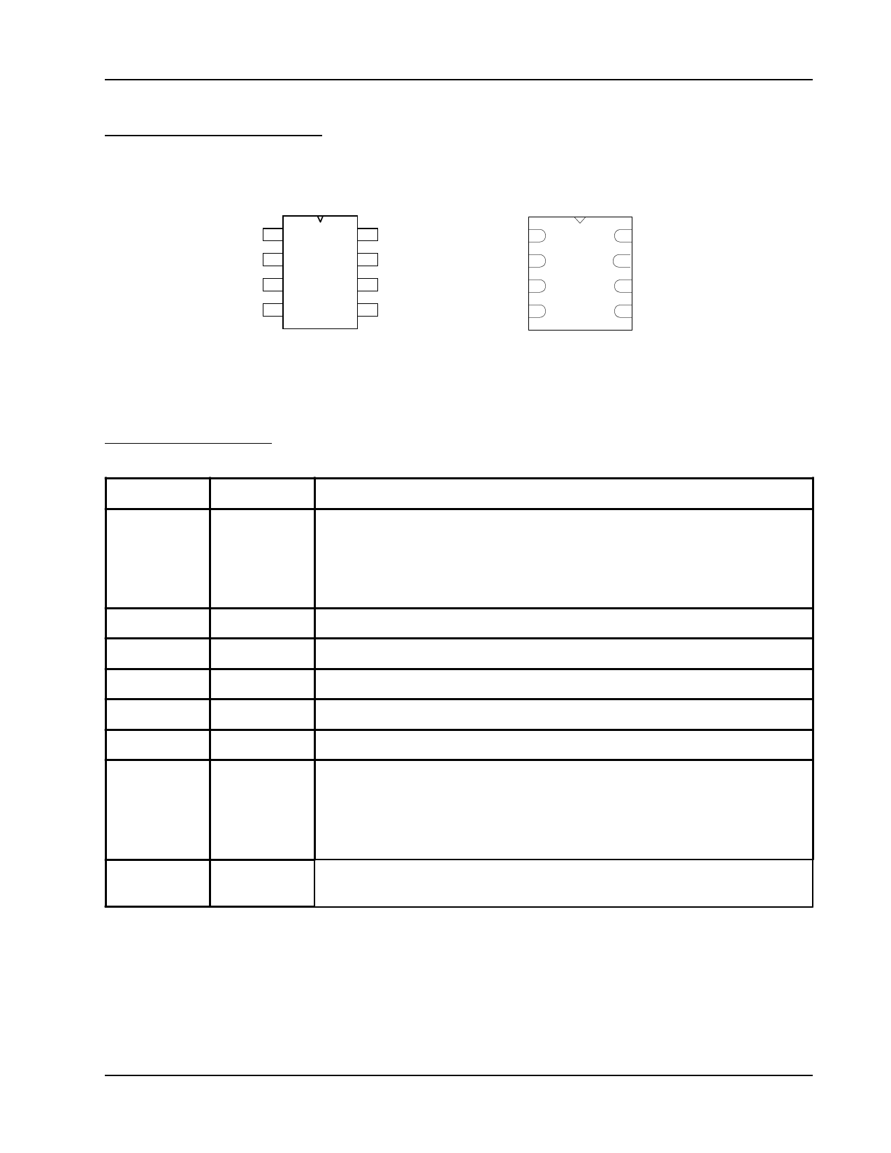
CONNECTION DIAGRAMS
Pm25LV010/020/040
CE#
1
SO
2
WP#
3
GND
4
8
Vcc
7
HOLD#
6
SCK
5
SI
8-Pin SOIC
CE# 1
SO 2
WP# 3
GND 4
8 Vcc
7 HOLD#
6 SCK
5 SI
8-Contact WSON
PIN DESCRIPTIONS
SYMBOL
TYPE
CE#
INPUT
SCK
SI
SO
GND
Vcc
INPUT
INPUT
OUTPUT
WP#
INPUT
HOLD#
INPUT
DESCRIPTION
Chip Enable: CE# goes low activates the devices internal circuitries for
device operation. CE# goes high deselects the devices and switches into
standby mode to reduce the power consumption. When the devices are not
selected, data will not be accepted via the serial input pin (Sl), and the
serial output pin (SO) will remain in a high impedance state.
Serial Data Clock
Serial Data Input
Serial Data Output
Ground
Device Power Supply
Write Protect: A hardware program/erase protection for all or partial of
memory array. When the WP# pin is pulled to low, whole or partial of
memory array is write protected depends on the setting of BP2, BP1 and
BP0 bits in the Status Register. When the WP# is pulled high, the devices
are not write protected.
Hold: Pause serial communication with the master device without resetting
the serial sequence.
Programmable Microelectronics Corp.
2
Issue Date: July, 2005, Rev: 1.2
Share Link: