LD7576JPS Просмотр технического описания (PDF) - Unspecified
Номер в каталоге
Компоненты Описание
производитель
LD7576JPS Datasheet PDF : 20 Pages
| |||
LD7576/76H/76J/76K
Application Information
Operation Overview
As long as the green power requirement becomes a trend
and the power saving is getting more and more important for
the switching power supplies and switching adaptors, the
traditional PWM controllers are not able to support such new
requirements. Furthermore, the cost and size limitation force
the PWM controllers need to be powerful to integrate more
functions to reduce the external part counts. The LD7576X
series are ideal for these applications to provide an easy
and cost effective solution; its detailed features are
described as below.
Internal High-Voltage Startup Circuit and
Under Voltage Lockout (UVLO)
will be enabled to supply 1mA current. Meanwhile, the Vcc
supply current is as low as 100μA that most of the HV
current is adopted to charge the Vcc capacitor. By using
such configuration, the turn-on delay time will be almost
same no matter under low-line or high-line conditions.
As the Vcc voltage rises higher than UVLO(on) to power on
the LD7576X series and further to deliver the gate drive
signal, the high-voltage current source will be disabled and
the supply current is provided from the auxiliary winding of
the transformer. Therefore, it would eliminate the power
loss on the startup circuit and perform highly power saving.
An UVLO comparator is embedded to detect the voltage on
the Vcc pin to ensure the supply voltage enough to power
on the LD7576X series PWM controller and in addition to
drive the power MOSFET. As shown in Fig. 14, a
hysteresis is provided to prevent the shutdown from the
voltage dip during startup. The turn-on and turn-off
threshold level are set at 16V and 10.0V, respectively.
Vcc
UVLO(on)
UVLO(off)
t
HV Current
1mA
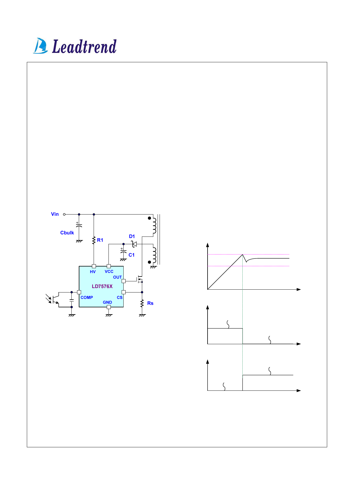
Fig. 13
The traditional circuit provides the startup current through a
startup resistor to power up the PWM controller. However, it
consumes too significant power to meet the current power
saving requirement. In most cases, startup resistors carry
large resistance. And larger resistance takes longer startup
time.
To achieve the optimized topology, as shown in figure 13,
LD7576X series are implemented with a high-voltage
startup circuit for such requirement. During the startup, a
high-voltage current source sinks current from the bulk
capacitor to provide the startup current as well as charge the
Vcc capacitor C1. During the startup transient, the Vcc
drops lower than the UVLO threshold so the current source
Vcc current
Startup Current
(<100uA)
~ 0mA (off)
t
Operating Current
(Supply from Auxiliary Winding)
Fig. 14
Current Sensing, Leading-Edge Blanking and
the Negative Spike on CS Pin
The typical current mode PWM controller feedbacks both
current signal and voltage signal to close the control loop
Leadtrend Technology Corporation
LD7576-DS-03 December 2007
10
www.leadtrend.com.tw
Share Link: 