IL710T Просмотр технического описания (PDF) - Unspecified
Номер в каталоге
Компоненты Описание
производитель
IL710T Datasheet PDF : 8 Pages
| |||
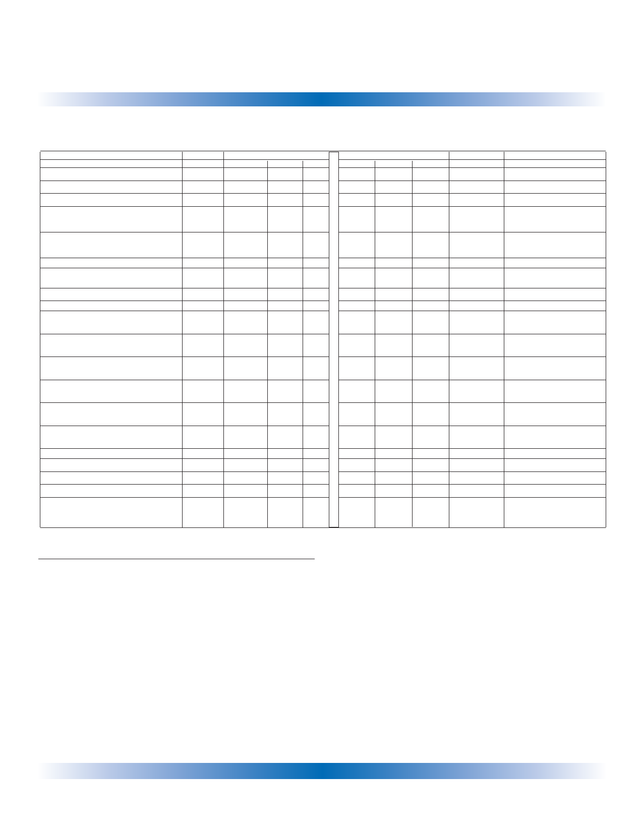
IL710TISOLOOP®
Electrical Specifications
Electrical Specifications are Tmin to Tmax unless otherwise stated.
Parameter
Symbol 3.0-3.6 V Specifications
DC Specifications
Min.
Typ. Max.
Input Quiescent Supply Current
IDD1
8
10
Output Quiescent Supply Current
Logic Input Current
Logic High Output Voltage
IDD2
II
VOH
3.3 4
-10
10
VDD2-0.1 VDD2
0.8*VDD2 VDD2-0.5
Logic Low Output Voltage
VOL
0 0.1
0.5 0.8
Switching Specifications
Dynamic Current Consumption(6)
300
420
Maximum Data Rate
Pulse Width
Propagation Delay
Input to Output (High to Low)
Propagation Delay
Input to Output (Low to High)
Propagation Delay Enable to Output
(High to High Impedance)
Propagation Delay Enable to Output
(Low to High Impedance)
Propagation Delay Enable to Output
(High Impedance to High)
Propagation Delay Enable to Output
(High Impedance to Low)
Pulse Width Distortion(2)
Propagation Delay Skew(3)
Output Rise Time (10-90%)
Output Fall Time (10-90%)
Common Mode Transient
Immunity (Output Logic High or
Logic Low) (4)
PW
tPHL
tPLH
tPHZ
tPLZ
tPZH
tPZL
tPSK
tR
tF
|CMH|
|CML|
100
110
10
12 18
12 18
3
5
3
5
3
5
3
5
2
3
4
6
2
4
2
4
20
30
4.5-5.5 V Specifications
Min. Typ. Max.
10
15
5
6
-10
10
VDD2-0.1 VDD2
0.8*VDD2 VDD2-0.5
0
0.1
0.5
0.8
500
640
100 110
10
10
15
10
15
3
5
3
5
3
5
3
5
2
3
4
6
1
3
1
3
20
30
Notes:
1. Absolute Maximum ambient operating temperature means the
device will not be damaged if operated under these conditions. It
does not guarantee performance.
2. PWD is defined as | tPHL - tPLH |. %PWD is equal to the PWD
divided by the pulse width.
3. tPSK is equal to the magnitude of the worst case difference in tPHL
and/or tPLH that will be seen between units at 25OC.
4. CMH is the maximum common mode voltage slew rate that can be
sustained while maintaining VO > 0.8 VDD2. CML is the maximum
common mode input voltage that can be sustained while
maintaining VO < 0.8 V. The common mode voltage slew rates
apply to both rising and falling common mode voltage edges.
5. Device is considered a two terminal device:
pins 1-4 shorted and pins 5-8 shorted.
6. Dynamic current is consumed on the VDD1 supply only.
Units
µA
mA
µA
V
V
µA/MHz
MBd
ns
ns
ns
ns
ns
ns
ns
ns
ns
ns
kV/µs
Test Conditions
IO =-20 µA, VI =VIH
IO = -4 mA, VI =VIH
IO = 20 µA, VI =VIL
IO = 4 mA, VI =VIL
CL = 15 pF
CL = 15 pF
CL = 15 pF
CL = 15 pF
CL = 15 pF
CL = 15 pF
CL = 15 pF
CL = 15 pF
CL = 15 pF
CL = 15 pF
Vcm = 300V
3
NVE Corporation 11409 Valley View Road Eden Prairie, MN 55344-3617 USA Telephone: (952) 829-9217 Fax: (952) 829-9189 Internet: www.isoloop.com
Share Link: 