HFBR-2464K –ü—Ä–æ—Å–º–æ—Ç—Ä —Ç–µ—Ö–Ω–∏—á–µ—Å–∫–æ–≥–æ –æ–ø–∏—Å–∞–Ω–∏—è (PDF) - HP => Agilent Technologies
–ù–æ–º–µ—Ä –≤ –∫–∞—Ç–∞–ª–æ–≥–µ
–ö–æ–º–ø–æ–Ω–µ–Ω—Ç—ã –û–ø–∏—Å–∞–Ω–∏–µ
–ø—Ä–æ–∏–∑–≤–æ–¥–∏—Ç–µ–ª—å
HFBR-2464K
HP => Agilent Technologies

HFBR-2464K Datasheet PDF : 31 Pages
| |||
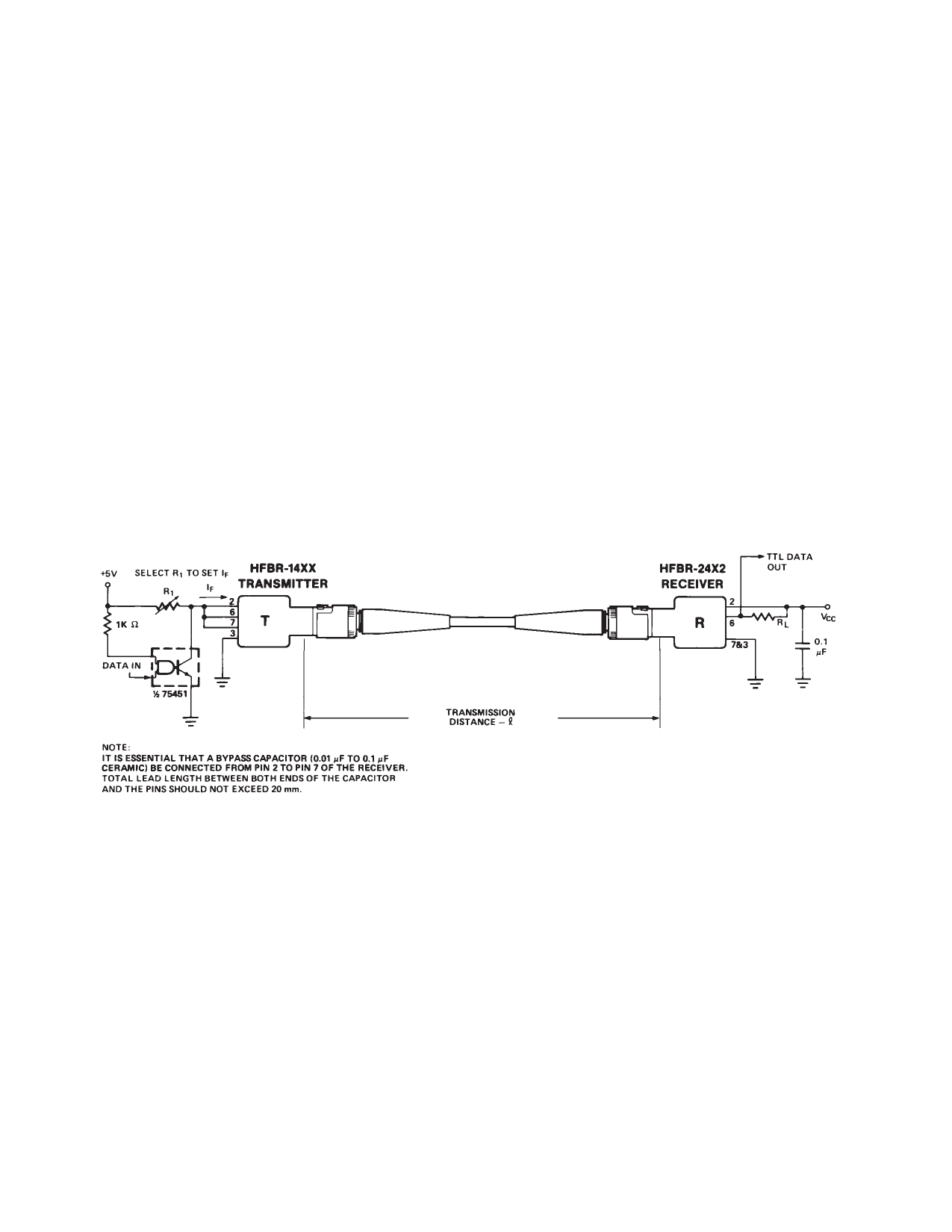
5 MBd Logic Link Design
If resistor R1 in Figure 2 is
70.4 Ω, a forward current IF of
48 mA is applied to the HFBR-
14X4 LED transmitter. With IF =
48 mA the HFBR-14X4/24X2
logic link is guaranteed to work
with 62.5/125 µm fiber optic
cable over the entire range of 0
to 1750 meters at a data rate of
dc to 5 MBd, with arbitrary data
format and pulse width distortion
typically less than 25%. By
setting R1 = 115 Ω, the transmit-
ter can be driven with IF = 30 mA,
if it is desired to economize on
power or achieve lower pulse
distortion.
The following example will illus-
trate the technique for selecting
the appropriate value of IF and R1.
Maximum distance required
= 400 meters. From Figure 3 the
drive current should be 15 mA.
From the transmitter data
VF = 1.5 V (max.) at IF = 15 mA
as shown in Figure 9.
R1
=
V–C–C––-–V–F–
IF
=
5––V––-–1–.–5–V–
15 mA
R1 = 233␣ Ω
The curves in Figures 3, 4, and 5
are constructed assuming no in-
line splice or any additional
system loss. Should the link
consists of any in-line splices,
these curves can still be used to
calculate link limits provided they
are shifted by the additional
system loss expressed in dB. For
example, Figure 3 indicates that
with 48 mA of transmitter drive
current, a 1.75 km link distance
is achievable with 62.5/125 µm
fiber which has a maximum
attenuation of 4 dB/km. With
2 dB of additional system loss, a
1.25 km link distance is still
achievable.
Figure 2. Typical Circuit Configuration.
56
Share Link: