MPU6050 Просмотр технического описания (PDF) - Unspecified
Номер в каталоге
Компоненты Описание
производитель
MPU6050 Datasheet PDF : 13 Pages
| |||
MPU-6000/MPU-6050 EV Board User Guide
Document Number: AN-MPU-6000EVB-00
Revision: 01
Release Date: 1/12/2011
7.1 Connecting the FSYNC Line
The FSYNC line is intended for use in a camera’s image-stabilization system. It is an input
from the camera platform to the EV Board, and is intended to synchronize the MPU-60X0
serial bus transfer with the master timing set by the camera system. FSYNC can originate
from the host processor via JP14 pin-21, or from JP13 pin-10. There is no external pull-up
termination for the FSYNC line.
7.2 Serial bus Levels, Speeds and Terminations
The MPU-60X0 supports I²C up to 400kHz, and MPU-6000 supports SPI up to 1MHz serial
clock rates. The I²C bus open drain pull up resistors are connected to either 3.0V or an
external provided Vcc (3V or 5V depends on user). The pull up level is selected by JP6.
Please refer to Table 3. Power Selection Jumpers.
8. Data Gathering Options
The MPU-60X0 Digital Sensor Data is available at the User Header. Alternatively, for connectivity
with a host PC, an InvenSense ARM Processor Board may be used.
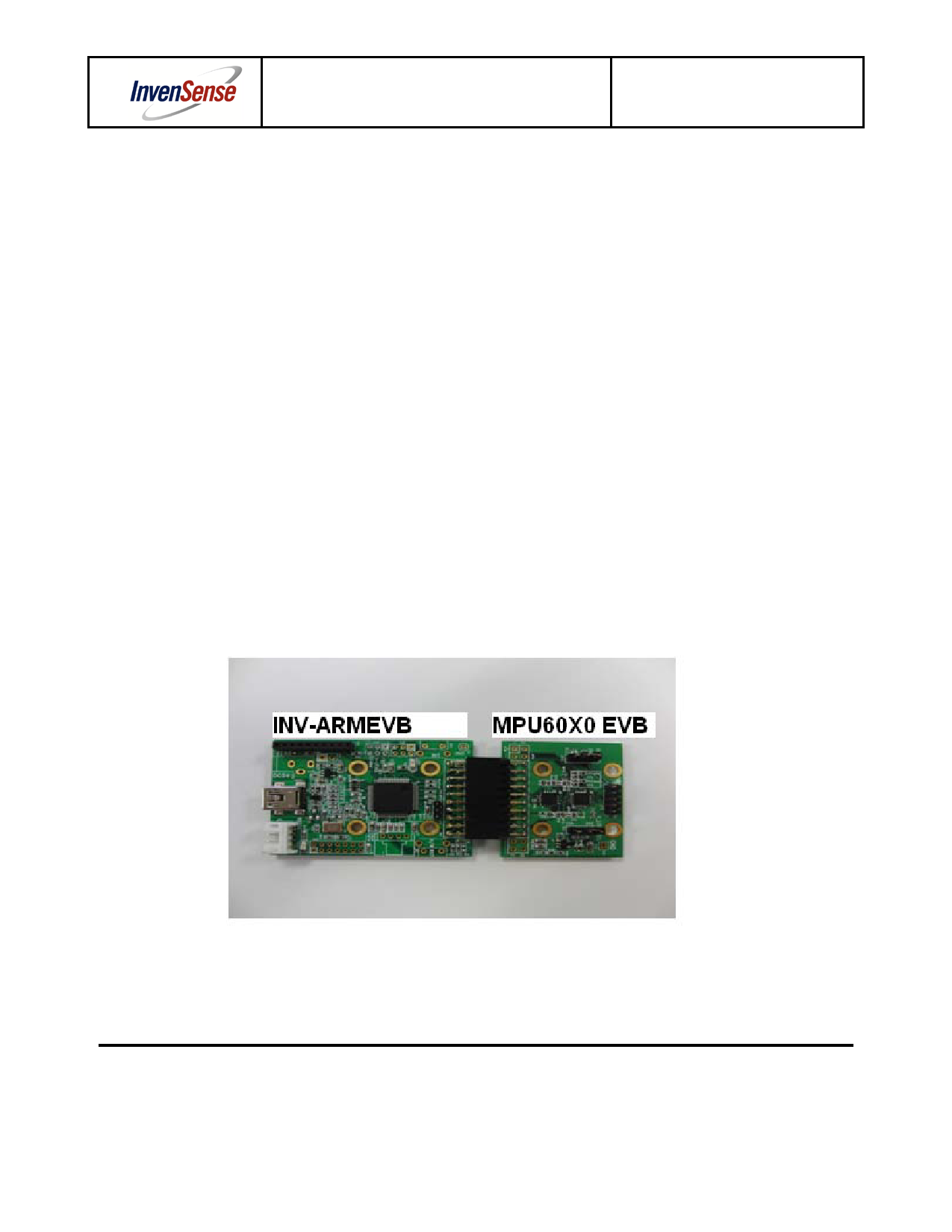
8.1 Connection to ARM EVB
For communications via USB to a host computer, the MPU-60X0 EVB can be connected to
InvenSense’s ARM processor board, the INV-ARMEVB.
The photo below shows the connection of MPU-60X0 to INV-ARMEVB. Connection between
the two boards is made via the user header.
Figure 4. MPU-60X0 EVB connected to ARM Board
InvenSense, Inc., 1197 Borregas Ave., Sunnyvale, Ca 94089, USA
11
Tel: +1 (408) 988-7339 Fax: +1 (408) 988-8104
Website: http//www.invensense.com
AN-MPU6000-EVB-00
©2011 InvenSense, Inc. All rights reserved.
Share Link: 