AT43311 Просмотр технического описания (PDF) - Atmel Corporation
Номер в каталоге
Компоненты Описание
производитель
AT43311 Datasheet PDF : 24 Pages
| |||
AT43311
visual feedback. The default state of STAT[1:4] is inactive.
After a port is enabled AT43311 will assert the port’s
STAT[1:4].
Oscillator and Phase-Locked-Loop
To reduce EMI and power dissipation in the system, the
AT43311 on-chip oscillator is designed to operate with a 6
MHz external crystal. An on-chip PLL generates the high
frequency for the clock/data separator of the Serial Inter-
face Engine. In the suspended state, the oscillator circuitry
is turned off.
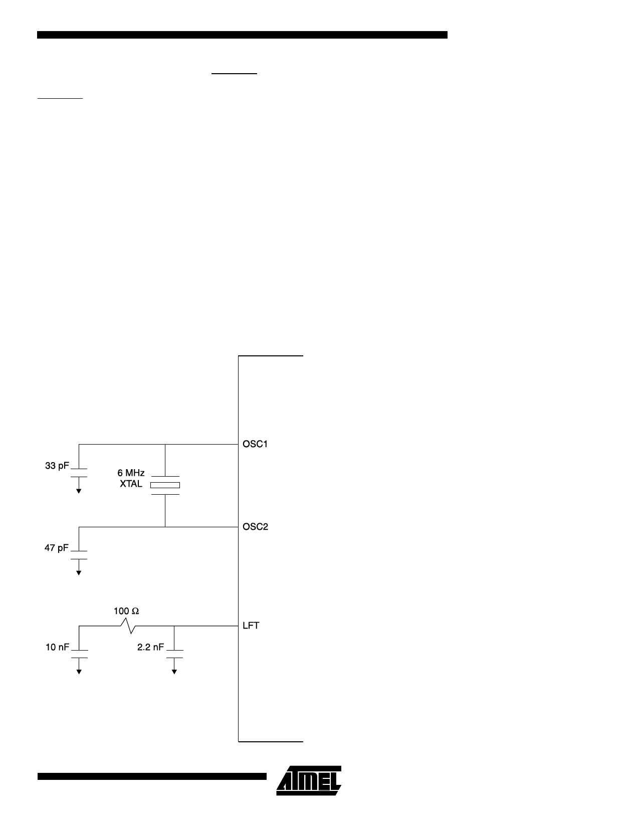
A 6 MHz parallel resonance quartz crystal with a load
capacitance of approximately 10 pF is recommended. If the
crystal load capacitor is larger, external capacitors added to
pins OSC1 and OSC2 are recommended. The values for
these capacitors depends on the crystal and the layout of
the board, but typically are 33 pF at OSC1 and 47 pF at
OSC2. If the crystal used cannot tolerate the drive levels of
the oscillator, a series resistor between OSC2 and the crys-
tal pin may be used.
Figure 2. Oscillator and PLL Connection
Figure 2 shows how to properly connect the oscillator for
the AT43311. Ceramic resonators are not recommended
due to the frequency stability required by the USB specifi-
cation (0.25%).
If desired, the clock can be externally sourced. To clock
externally, connect the clock source to the OSC1 pin, while
leaving the OSC2 pin floating. The switching level at the
OSC1 pin can be as low as 0.47V (see electrical specifica-
tions). A CMOS device is required to drive this pin to main-
tain good noise margins at the low switching level.
For proper operation of the PLL, see Figure 1–Power Sup-
ply Connection.
To provide the best operating condition for the AT43311,
careful consideration of the power supply connections are
recommended. Use short, low impedance connections to
all power supply lines: VCC5, VCC3, VCCA, and VSS with
0.1 µF decoupling capacitors of high quality adjacent to the
device pins.
Descriptors
The Hub Controller supports the following standard USB
descriptors: Device, Configuration, Interface, and Endpoint
Descriptors, as well as the class specific Hub Descriptor.
All the required Standard Requests and Hub Class-Specific
Requests are supported by the AT43311’s Hub Controller.
7
Share Link: 