XRT4000 Просмотр технического описания (PDF) - Exar Corporation
Номер в каталоге
Компоненты Описание
производитель
XRT4000 Datasheet PDF : 46 Pages
| |||
XRT4000
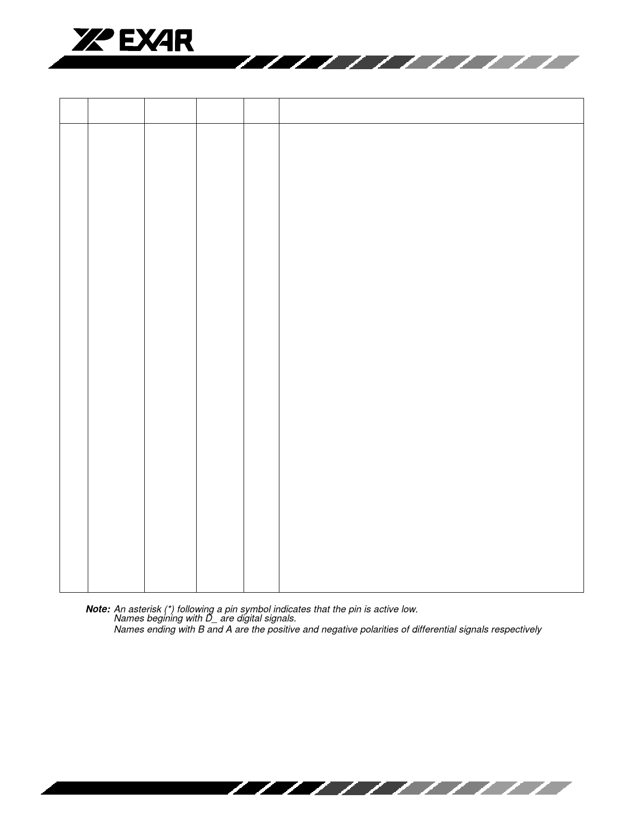
Pin Symbol
DTE
DCE Type Function
#
Mode
Mode
64 REG_CLK
I Clock - For Transmitter 5, 8 input register. Internal 20KΩ pull-up
65 2CK/3CK*
I 2 or 3 Clock Select - Internal 20KΩ pull-up
Logic Don’t Care: 1 Clock When Mode = X.21 (M2, M1, M0= 011)
Logic 0: 3 Clocks When Mode ≠ X.21 (M2, M1, M0 ≠ 011)
Logic 1: 2 Clocks When Mode ≠ X.21 (M2, M1, M0 ≠ 011)
66 EN_OSC*
I Test Oscillator Enable - Active Low; Logic 0: Oscillator Enabled.
Logic 1: Oscillator Disabled. Internal 20KΩ pull-up
67 CKINV*
I Invert Clock - Active Low; Logic 0: Clock Inverted.
Logic 1: Clock not Inverted. Internal 20KΩ pull-up
68 DTINV*
I Invert Data - Active Low; Logic 0: Data Inverted.
Logic 1: Data not Inverted. Internal 20KΩ pull-up
69
VSS
Digital VSS for Transmitter 1, 2, 3 Output Drivers;
Connect to -6V
70
GND
Digital GND for Transmitter 1, 2, 3 Output Drivers
71
VDD
Digital VDD for Transmitter 1, 2, 3 Output Drivers;
Connect to +5V
72
VDD
Analog VDD for Transmitter 1, 2; Connect to +5V
73
VSS
Analog VSS for Transmitter 1, 2; Connect to -6V
74
GND
Analog GND for Transmitter 1, 2 “T” termination
75
TX1D
D_TXD D_RXD I Transmitter 1- Digital Data Input from equipment
76 CM_TX1
O AC GND - Transmitter 1 Output Termination center tap in V.35 mode
77
TX1B
TXDB RXDB O Transmitter 1 - Positive Data Differential Output to line
78
TX1A
TXDA RXDA O Transmitter 1 - Negative Data Differential Output to line
79
TX2A
SCTEA RXCA O Transmitter 2 - Negative Data Differential Output to line
80
TX2B
SCTEB RXCB O Transmitter 2 - Positive Data Differential Output to line
81 CM_TX2
O AC GND - Transmitter 2 Output Termination center tap in V.35 mode
82
TX2D D_SCTE D_RXC I Transmitter 2 - Digital Data Input from equipment
83
VDD
Digital VDD for Receiver and Transmitter 1, 2, 3; Connect to +5V
84
TX3D
D_X
D_TXC
I DTE Mode - Input not used
DCE Mode - Transmitter 3 - Digital Data Input from equipment
85
VSS
Digital VSS for Receiver and Transmitter 1, 2, 3; Connect to -6V
86 CM_TR3
O DTE Mode - AC GND - Transmitter 3 Output Termination center tap
in V.35 mode
DCE Mode - AC GND - Receiver 3 Input Termination center tap in
V.35 mode
87
TR3A
TXCA TXCA I/O DTE Mode - Receiver 3 - Negative Data Differential Input from line.
DCE Mode - Transmitter 3 - Negative Data Differential Output to
line.
Note: An asterisk (*) following a pin symbol indicates that the pin is active low.
Names begining with D_ are digital signals.
Names ending with B and A are the positive and negative polarities of differential signals respectively
Rev. 1.00
-8-
Share Link: 