RF3110 Просмотр технического описания (PDF) - RF Micro Devices
Номер в каталоге
Компоненты Описание
производитель
RF3110 Datasheet PDF : 12 Pages
| |||
Preliminary
RF3110
Theory of Operation
Overview
The RF3110 is a triple-band GSM/DCS/PCS power
amplifier module that incorporates an indirect closed
loop method of power control. This simplifies the
phone design by eliminating the need for the compli-
cated control loop design. The indirect closed loop is
fully self contained and required does not require loop
optimization. It can be driven directly from the DAC out-
put in the baseband circuit.
Theory of Operation
The indirect closed loop is essentially a closed loop
method of power control that is invisible to the user.
Most power control systems in GSM sense either for-
ward power or collector/drain current. The RF3110
does not use a power detector. A high-speed control
loop is incorporated to regulate the collector voltages
of the amplifier while the stages are held at a constant
bias. The VRAMP signal is multiplied and the collector
voltages are regulated to the multiplied VRAMP voltage.
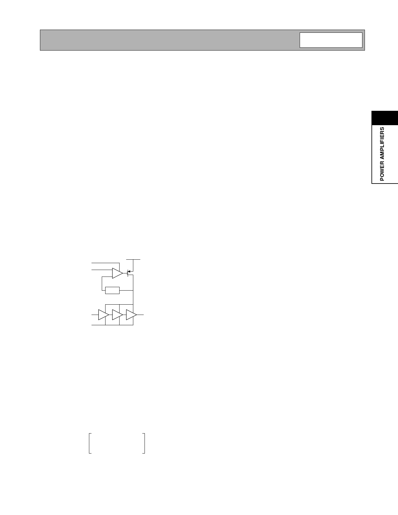
The basic circuit is shown in the following diagram.
TX ENABLE
VRAMP
VBATT
H(s)
RF IN
TX ENABLE
RF OUT
By regulating the power, the stages are held in satura-
tion across all power levels. As the required output
power is decreased from full power down to 0dBm, the
collector voltage is also decreased. This regulation of
output power is demonstrated in Equation 1 where the
relationship between collector voltage and output
power is shown. Although load impedance affects out-
put power, supply fluctuations are the dominate mode
of power variations. With the RF3110 regulating collec-
tor voltage, the dominant mode of power fluctuations is
eliminated.
PdBm
=
10 ⋅ log
-(--2----⋅---V----C----C----–-----V----S--A----T---)--2-
8 ⋅ RLOAD ⋅ 10–3
(Eq. 1)
There are several key factors to consider in the imple-
mentation of a transmitter solution for a mobile phone.
Some of them are:
• Effective efficiency (ηeff)
2
• Current draw and system efficiency
• Power variation due to Supply Voltage
• Power variation due to frequency
• Power variation due to temperature
• Input impedance variation
• Noise power
• Loop stability
• Loop bandwidth variations across power levels
• Burst timing and transient spectrum trade offs
• Harmonics
Talk time and power management are key concerns in
transmitter design since the power amplifier has the
highest current draw in a mobile terminal. Considering
only the power amplifier’s efficiency does not provide a
true picture for the total system efficiency. It is impor-
tant to consider effective efficiency which is repre-
sented by ηEFF. (ηEFF considers the loss between the
PA and antenna and is a more accurate measurement
to determine how much current will be drawn in the
application). ηEFF is defined by the following relation-
ship (Equation 2):
m
å PN – PIN
ηEFF
=
n----=-----1-----------------------
PDC
⋅
100
(Eq. 4)
Where Pn is the sum of all positive and negative RF
power, PIN the input power and PDC is the delivered
DC power. In dB the formula becomes (Equation 3):
P----P---A----+-----P----L---O---S---S
-P---I--N-
ηEFF
=
-1--0-------------1---0-------------–-----1---0----1--0--
VBAT ⋅ IBAT ⋅ 10
(Eq. 3)
Rev A0 010921
2-268
Share Link: 