NCP1205 Просмотр технического описания (PDF) - ON Semiconductor
Номер в каталоге
Компоненты Описание
производитель
NCP1205
ON Semiconductor

NCP1205 Datasheet PDF : 17 Pages
| |||
NCP1205
APPLICATION INFORMATION
Introduction
By implementing a unique smooth frequency reduction
technique, the NCP1205 represents a major leap toward
low−power Switchmode Power Supply (SMPS) integrated
management. The circuit combines free−running operation
with minimum drain−source switching (so−called valley
switching), which naturally reduces the peak current stress
as well as the ElectroMagnetic Interferences (EMI). At
nominal output power, the circuit implements a traditional
current−mode SMPS whose peak current setpoint is given
by the feedback signal. However, rather than keeping the
switching frequency constant, each cycle is initiated by the
end of the primary demagnetization. The system therefore
operates at the boundary between Discontinuous
Conduction Mode (DCM) and Continuous Conduction
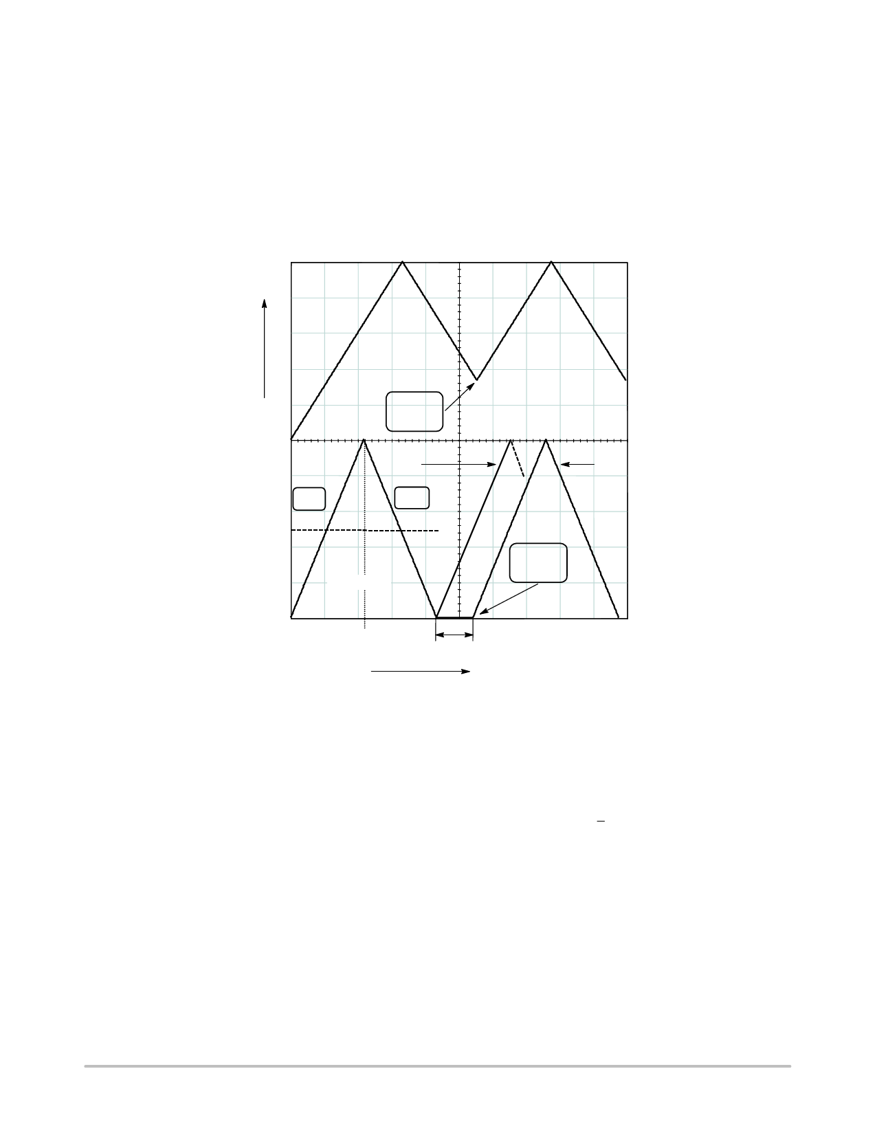
Mode (CCM). Figure 10 details this terminology:
L > Lc
IL
Not 0 at
Turn ON
IP
L = Lc
0
L < Lc
ON
IL(avg)
OFF
Borderline
0 Before
Turn ON
0
D/Fs
Dead−Time
Time
Figure 10. Defining the Conduction Mode, Discontinuous, Continuous and Borderline
When the output power demands decreases, the natural
switching frequency raises. As a natural result, switching
losses also increase and degrade the SMPS efficiency. To
overcome this problem, the maximum switching frequency
of the NCP1205 is clamped to typically 125 kHz. When the
free running mode (also called Borderline Control Mode,
BCM) reaches this clamp value, an internal
Voltage−Controlled Oscillator (VCO) takes over and starts
to decrease the switching frequency: we are in Variable
Frequency Mode (VFM). Please note that during this
transition phase, the peak current is not fixed but is still
decreasing because the output power demand does. At a
given state, the peak current reaches a minimum peak
(typically 250 mV/Rsense), and cannot go further down: the
switching frequency continues its decrease down to a
possible minimum of 0 Hz (the IC simply stops switching).
During normal free−running operation and VFM, the
controller always ensures single or multiple drain−source
valley switching. We will see later on how this is internally
implemented.
The FLYBACK operation is mainly defined through a
simple formula:
Pout
+
1
2
·
Lp · Ip2
·
Fsw
(eq. 1)
With:
Lp the primary transformer inductance (also called the
magnetizing inductance)
Ip the peak current at which the MOSFET is turned off
Fsw the nominal switching frequency
To adjust the transmitted power, the PWM controller can
play on the switching frequency or the peak current setpoint.
To refine the control, the NCP1205 offers the ability to play
on both parameters either altogether on an individual basis.
http://onsemi.com
9
Share Link: