HFBR-4663 Просмотр технического описания (PDF) - HP => Agilent Technologies
Номер в каталоге
Компоненты Описание
производитель
HFBR-4663 Datasheet PDF : 15 Pages
| |||
correct RTSET resistor:
( ) RTSET= –5–2––m––A l62 Ω
IOUT
The transmitter enters the idle
state when it detects start of idle
on Tx+ and Tx- input pins. After
detecting the start of idle, the
transmitter switches to a 1 MHz
output idle signal.
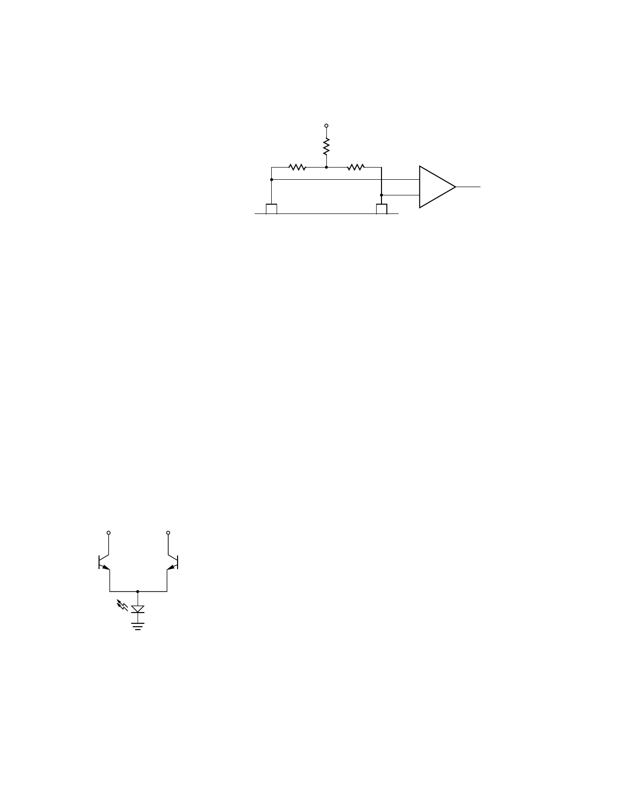
VCC
51 Ω
51 Ω
51 Ω
RTSET = 560 Ω
IOUT = 15.9 mA
ECL
VCCTx
TxOUT
Figure 3. Converting Optical LED Driver Output to Differential ECL.
The output current is switched
through the TxOUT pin during the
on cycle and the VCCTx pin during
the off cycle as shown in figure 2.
Since the sum of the current in
these two pins is constant, VCCTx
should be connected as close as
possible to the VCC connection for
the LED.
If not driving an optical LED
directly, a differential output can
be generated by tying resistors
from VCCTx and TxOUT to VCC as
shown in Figure 3. The minimum
voltage on these two pins should
not be less than VCC - 2 V.
VCCTx
TxOUT
IOUT
Figure 2. Fiber Optic LED Driver
Structure.
Reception
The input to the transceiver
comes from a fiber optic receiver
as shown in figure 1. At the start
of packet reception no more than
2.7 bits are received from the
fiber cable and not transmitted
onto the DI circuit. The receive
squelch will reject frequencies
lower than 2.51 MHz.
While in the unsquelch state, the
receive squelch circuit looks for
the start of idle signal at the end
of the packet. Start of idle occurs
when the input signal remains idle
for more than 160 ns. When start
of idle is detected, the receive
squelch circuit returns to the
squelch state and the start of idle
signal is output on the DI circuit
(Rx+, Rx-).
Collision
Whenever the receiver and the
transmitter are active at the same
time the chip will activate the
collision output, except when
loopback is disabled (LBDIS =
Vcc). The collision output is a
differential square wave matching
the AUI specifications and
capable of driving a 78 Ω load.
The frequency of the square wave
is 10 MHz ± 15% with a 60/40 to
40/60 duty cycle. The collision
oscillator also is activated during
SQE Test and jabber.
Loopback
The loopback function emulates a
10BASE-T transceiver whereby
the transmit data sent by the DTE
is looped back over the AUI
receive pair. Some LAN
controllers use this loopback
information to determine whether
a MAU is connected by
monitoring the carrier sense while
transmitting. The software can
use this loopback information to
determine whether a MAU is
connected to the DTE by
checking the status of carrier
sense after each packet
transmission.
When data is received by the chip
while transmitting, a collision
condition exits. This will cause
the collision oscillator to turn on
and the data on the DI pair will
follow VIN+, VIN-. After a collision
is detected, the collision oscillator
will remain on until either DO or
VIN+, VIN- go idle.
Loopback can be disabled by
strapping LBDIS to VCC. In this
mode the chip operates as a full
duplex transmitter and receiver,
and collision detection is disabled.
A loopback through the
transceiver can be accomplished
by tying the fiber transmitter to
the receiver.
85
Share Link: 