HGTP12N60D1 Просмотр технического описания (PDF) - Intersil
Номер в каталоге
Компоненты Описание
производитель
HGTP12N60D1 Datasheet PDF : 4 Pages
| |||
Specifications HGTP12N60D1
Electrical Specifications TC = +25oC, Unless Otherwise Specified
LIMITS
PARAMETERS
SYMBOL
TEST CONDITIONS
MIN
TYP MAX UNITS
Collector-Emitter Breakdown Voltage
BVCES
IC = 250µA, VGE = 0V
600
-
-
V
Collector-Emitter Leakage Voltage
ICES
VCE = BVCES
TC = +25oC
-
-
1.0
µA
VCE = 0.8 BVCES
TC = +125oC
-
-
4.0
mA
Collector-Emitter Saturation Voltage
VCE(SAT)
IC = IC90, VGE = 15V TC = +25oC
-
1.9
2.5
V
TC = +125oC
-
2.1
2.7
V
Gate-Emitter Threshold Voltage
VGE(TH)
IC = 250µA, VCE = VGE, TC = +25oC
3.0
4.5
6.0
V
Gate-Emitter Leakage Current
IGES
VGE = ±20V
-
-
±500
nA
Gate-Emitter Plateau Voltage
VGEP
IC = IC90, VCE = 0.5 BVCES
-
7.2
-
V
On-State Gate Charge
QG(ON)
IC = IC90,
VCE = 0.5 BVCES
VGE = 15V
VGE = 20V
-
45
60
nC
-
70
90
nC
Current Turn-On Delay Time
Current Rise Time
Current Turn-Off
tD(ON)I
tRI
tD(OFF)I
L = 500µH, IC = IC90, RG = 25Ω,
VGE = 15V, TJ = +150oC,
VCE = 0.8 BVCES
-
100
-
ns
-
150
-
ns
-
430
600
ns
Current Fall Time
tFI
-
430
600
ns
Turn-Off Energy (Note 1)
Thermal Resistance IGBT
WOFF
RθJC
-
1.8
-
mJ
-
-
1.67 oC/W
NOTE:
1. Turn-off Energy Loss (WOFF) is defined as the integral of the instantaneous power loss starting at the trailing edge of the input pulse and
ending at the point where the collector current equals zero (ICE = 0A). The HGTP12N60D1 was tested per JEDEC standard No. 24-1
Method for Measurement of Power Device Turn-off Switching Loss. This test method produces the true total Turn-off Energy Loss.
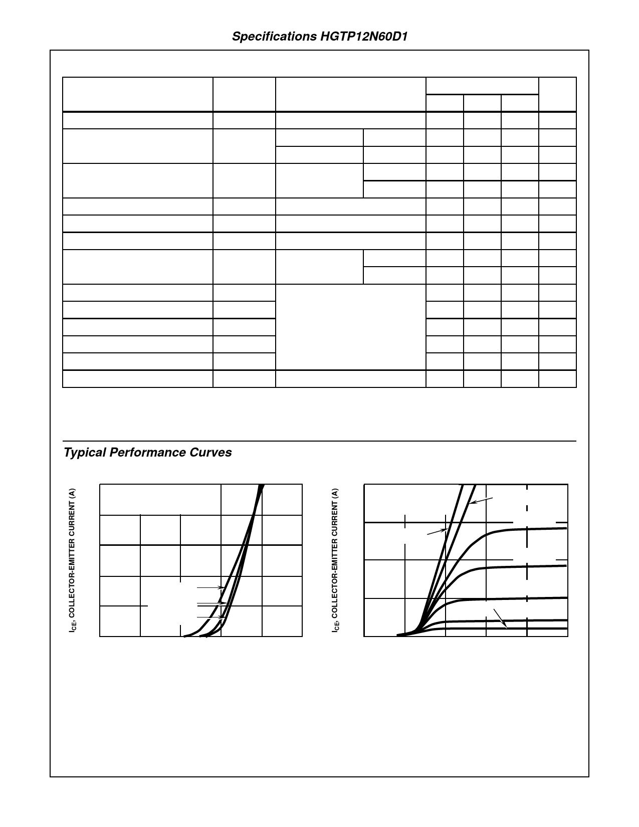
Typical Performance Curves
20
PULSE DURATION = 250µs
DUTY CYCLE < 0.5%
16 VCE = 10V
12
8
TC = +150oC
4
TC = +25oC
TC = -40oC
0
0
2
4
6
8
10
VGE, GATE-EMITTER VOLTAGE (V)
FIGURE 1. TRANSFER CHARACTERISTICS (TYPICAL)
20
PULSE DURATION = 250µs
DUTY CYCLE < 0.5%
TC = +25oC
15
VGE = 15V
10
VGE = 10V
VGE = 7.5V
VGE = 7.0V
VGE = 6.5V
5
VGE = 5.7V
VGE = 6.0V
0
0
1
2
3
4
5
VGE, COLLECTOR-EMITTER VOLTAGE (V)
FIGURE 2. SATURATION CHARACTERISTICS (TYPICAL)
3-39
Share Link: 