TN1215-800H Просмотр технического описания (PDF) - STMicroelectronics
Номер в каталоге
Компоненты Описание
производитель
TN1215-800H Datasheet PDF : 15 Pages
| |||
TN1215, TYN612, TYN812, TYN1012
Characteristics
Symbol
Table 4. Thermal resistance
Parameter
Rth(j-c)
Junction to case (DC)
Rth(j-a)
Junction to ambient (DC)
S(1) = 0.5 cm2
S(1) = 1.0 cm2
DPAK, IPAK, TO-220AB
DPAK
D²PAK
IPAK
TO-220AB
1. S = Copper surface under tab
Value
1.3
70
45
100
60
Unit
°C/W
°C/W
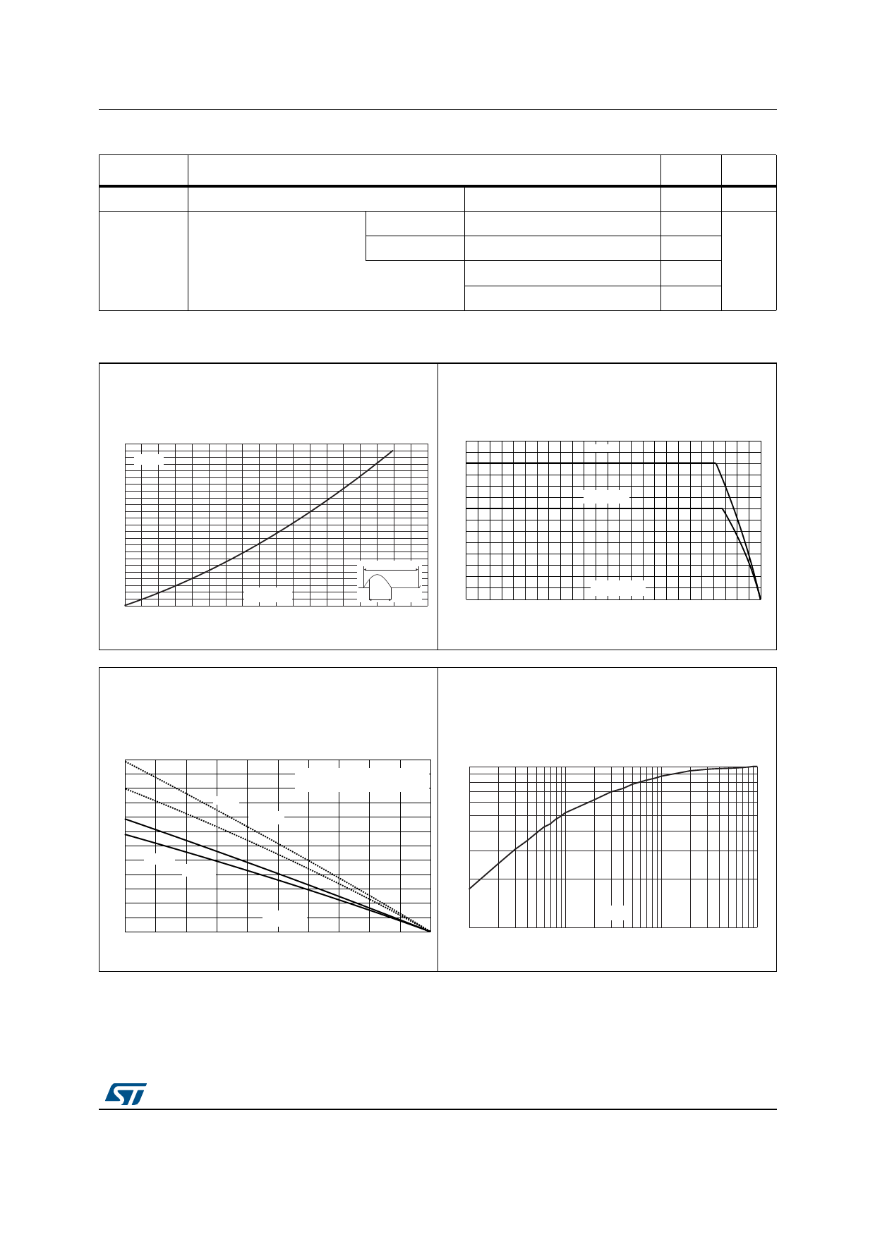
Figure 1. Maximum average power dissipation
versus average on-state current
Figure 2. Average and DC on-state current
versus case temperature
P(W)
12
,7
$9
$
11
α = 180°
10
9
8
7
6
5
4
3
360°
2
1
IT(AV)(A)
α
0
0
1
2
3
4
5
6
7
8
9
'&
D
7F
&
Figure 3. Average and DC on-state current
versus ambient temperature (DPAK)
Figure 4. [Relative variation of thermal
impedance junction to case versus pulse
duration
,7
$9
$
'HYLFHPRXQWHGRQ)5ZLWK
UHFRPPHQGHGSDGOD \RXW
'&
'ð3$.
K=[Zth(j-c)/Rth(j-c)]
1.0
0.5
Į
'3$.
0.2
7D
&
0.1
1E-3
tp(s)
1E-2
1E-1
1E+0
DocID7475 Rev 10
3/15
15
Share Link: 