SF3-DC18V Просмотр технического описания (PDF) - Matsushita Electric Works
Номер в каталоге
Компоненты Описание
производитель
SF3-DC18V
Matsushita Electric Works

SF3-DC18V Datasheet PDF : 7 Pages
| |||
SF
3) 4a4b Type
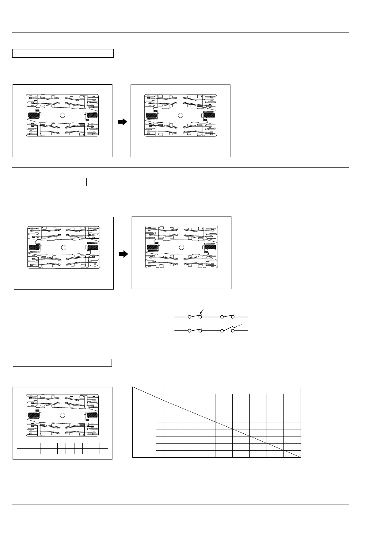
Internal Contacts Weld
If the internal contacts (nos. 2, 3, 6, and 7) weld, the armature becomes non-operational and the contact gaps of each of the four form
“a” contacts are maintained at greater than 0.5 mm .020 inch. Reliable isolation is thus ensured.
No.8
No.7
No.6
No.5
Non-energized
No.1
No.2
No.3
No.4
No.8
No.1
No.7
No.2
If the No. 2 contact welds.
Each of the four form "a" contacts (Nos. 1, 3, 5,
and 7) maintains a gap of greater than 0.5 mm
No.6
No.3 .020 inch.
No.5
No.4
Energized (when no. 2 contact is welded)
External Contacts Weld
If the external contacts (nos. 1, 4, 5, and 8) weld, gaps of greater than 0.5 mm .020 inch are maintained between adjacent contacts
and the coil returns to an non-energized state.
No.8
No.1
No.8
No.1 If the No. 1 contact welds.
The adjacent No. 2 contact maintains a gap of
No.7
No.2
No.7
No.2 greater than 0.5 mm .020 inch. The other con-
tacts, because the coil is not energized, return to
their normal return state; each of form “a” con-
No.6
No.3
No.6
No.3
tacts (nos. 3, 5, and 7) maintains a contact gap of
greater than 0.5 mm .020 inch; each of the form
No.5
No.4
No.5
No.4 “b” contacts (nos. 4, 6, and 8) return to a closed
state.
Energized
Non-energized (when no. 1 contact is welded)
If external connections are made in series.
Weld
Even if one of the contacts welds, because the
other contacts operate independently, the contact
gaps are maintained at greater than 0.5 mm .020
Energized
inch.
Non-energized
Contact gap
min 0.5 mm .020 inch
Contact Operation Table
The table below shows the state of the other contacts when the current through the welded form “a” contact is 0 V and the rated volt-
age is applied through the form “b” contact.
No.8
No.7
No.1
No.2
No.6
No.5
No.3
No.4
Contact No. No.1 No.2 No.3 No.4 No.5 No.6 No.7 No.8
Terminal No. 13–14 5–6 9–10 17–18 19–20 11–12 7–8 15–16
Contact No.
State of other contacts
Contact No.
1
2
3
4
5
6
7
8
1
>0.5 >0.5 ≠ >0.5 ≠ >0.5 ≠
2 >0.5
>0.5
>0.5
>0.5
3
>0.5
>0.5
>0.5
>0.5
Welded
terminal
4
≠
No. 5 >0.5
>0.5
≠
>0.5
>0.5
≠
≠ >0.5 ≠ >0.5
>0.5 >0.5 ≠
6 >0.5
>0.5
>0.5
>0.5
7
>0.5
>0.5
>0.5
>0.5
8 ≠ >0.5 ≠ >0.5 ≠ >0.5 >0.5
>0.5: contact gap
is kept at min. 0.5
mm .020 inch
≠: contact closed
Empty cells: either
closed or open
Note: Contact gaps are shown at the initial state.
If the contacts change state owing to loading/breaking it is necessary to check the actual loading.
For Cautions for Use, see Relay Technical Information (Page 48 to 76).
92/614/2000
All Rights Reserved, © Copyright Matsushita Electric Works, Ltd.
Go To Online Catalog
Share Link: